LED based light engine

a technology of led light engine and led light, which is applied in the direction of semiconductor devices for light sources, lighting and heating apparatus, and connection of coupling devices, etc., can solve the problems of increasing energy costs, short life, and large power consumption of light bulbs, and achieves efficient thermal management design, dissipation of led generated heat, and high efficiency

Inactive Publication Date: 2007-10-18
TALL TOWER LED
View PDF35 Cites 119 Cited by
  • Summary
  • Abstract
  • Description
  • Claims
  • Application Information

AI Technical Summary

Benefits of technology

[0011]The LED based light engine of the present disclosure utilizes, high power (3 Watt type) LEDs with optics to produce narrow, medium or wide illumination patterns and an electronic regulation circuit which converts line voltage (e.g. 115 VAC or 220 VAC) to the voltage required of a 3, 5, or other LED array (i.e. 12 volts, 20 volts, etc.), while maintaining a constant current of 700 mA, 1,000 mA or higher. To enable the LED based light engine of the present disclosure to be a screw-in replacement, the electronic regulation circuit is disposed internal to the housing of the engine. The challenge, when designing high power LED lamps, is to dissipate the LED generated heat as

Problems solved by technology

First, incandescent light bulbs use a relatively large amount of power compared to other lighting products which increase energy costs.
Second, incandescent light bulbs have a short life causing repetitive replacement costs.
Furthermore, since theses bulbs have a short life, labor costs will subsequently be effected by having maintenance personnel constantly replace the bulbs.
The disadvantages with this approach are that the 5 mm LEDs do not offer the same service life as higher power LEDs, large quantities of 20 mA surface mount LEDs are more expensive than using fewer high power LEDs, and the light pattern produced is more difficult to control when using a

Method used


Image

  • LED based light engine
  • LED based light engine
  • LED based light engine

Examples


Embodiment Construction

[0027]Preferred embodiments of the present disclosure will be described hereinbelow with reference to the accompanying drawings. In the following description, well-known functions or constructions are not described in detail to avoid obscuring the invention in unnecessary detail. Throughout the drawings, like reference numerals represent like elements.

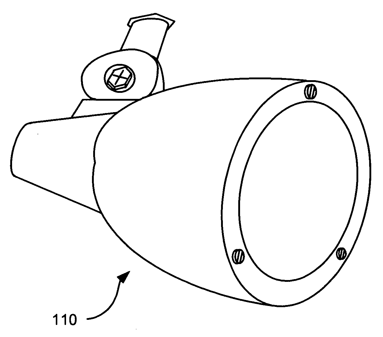
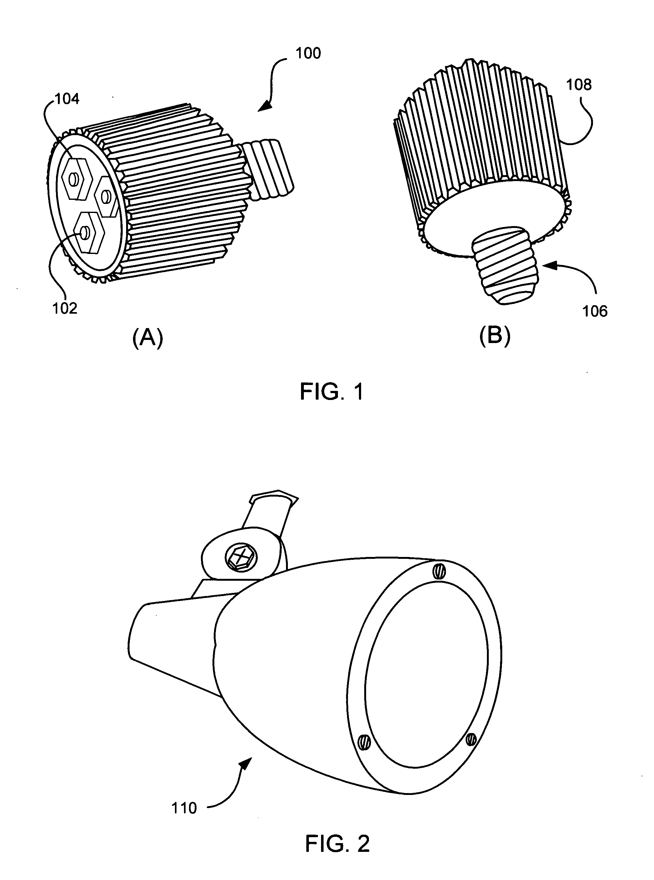
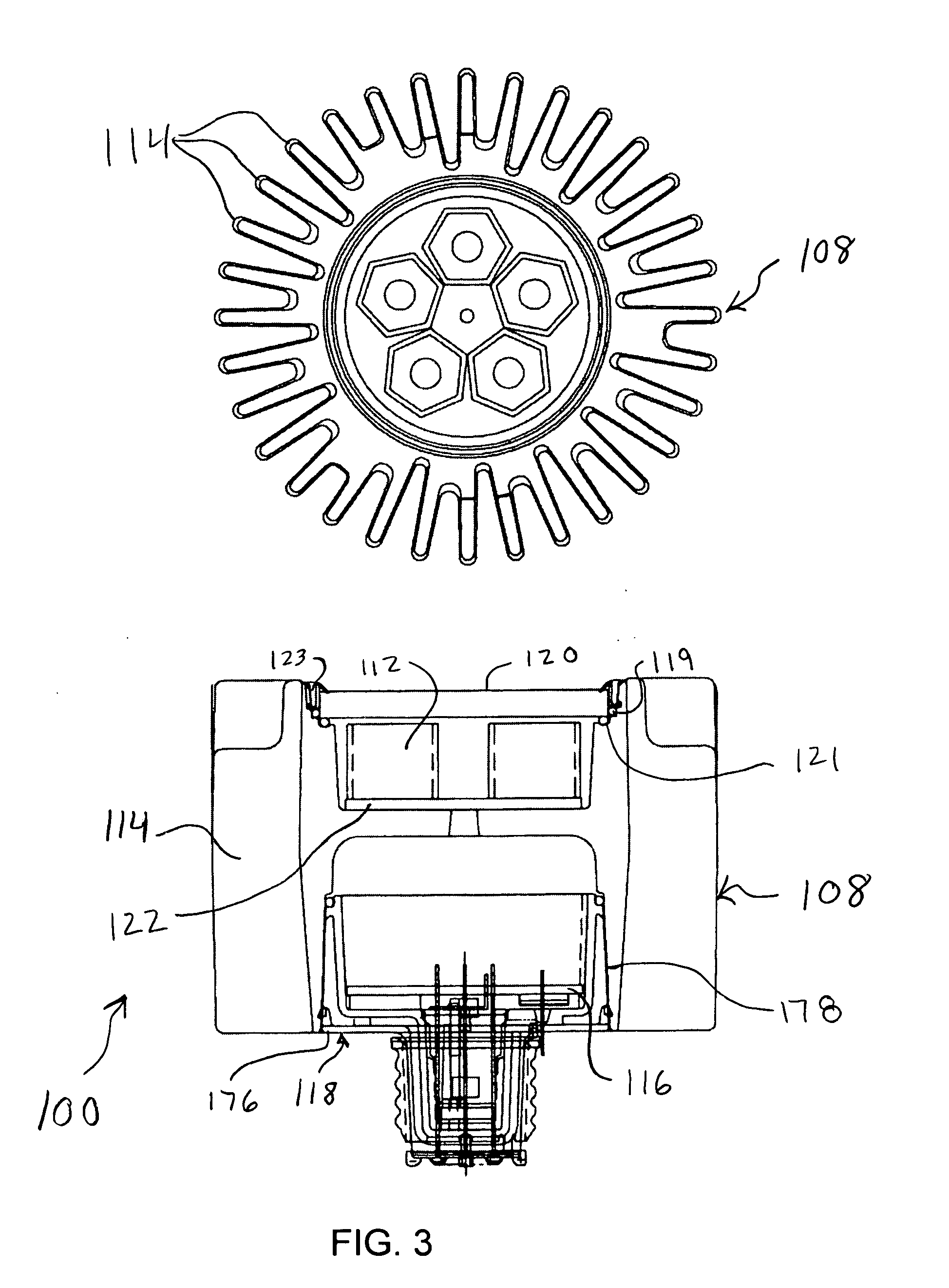
[0028]Referring to FIG. 1, an embodiment of the LED based light engine 100 of the present disclosure is illustrated as a replacement for a PAR20 lamp. The LED PAR20 lamp is intended to provide a much more energy efficient and reliable alternative to a standard incandescent 35 Watt PAR20 bulb. It is designed to provide approximately 50% energy savings and a 7 year service life. It will generate an amount of light approximately equivalent to the 35 Watt PAR20 bulb while using less than half of the energy (102 generating approximately 100 lumens each for a total of 300 lumens in generated light. It uses high efficiency optical elements 10...


PUM


Abstract

A light emitting diode (LED) based light engine that can replace a conventional PAR type bulb with no modifications to a host lighting fixture is provided. The light engine includes a thermally conductive housing including a generally cylindrical wall defining a cavity, an outer surface of the wall includes a plurality of axially radiating fins and disposed on an inner surface of the wall is an annular center wall dividing the cavity into a first, upper cavity and a second, lower cavity; a light module including at least one LED is disposed in the first, upper cavity and configured to contact the annular center wall, wherein heat generated by the at least one LED is conducted to the housing; and a current driver circuit arranged on a substrate is disposed in the second, lower cavity and electrically coupled to the light module.

Description

PRIORITY[0001]This application claims priority to an application entitled “LED BASED LIGHT ENGINE” filed in the United States Patent and Trademark Office on Apr. 12, 2006 and assigned Ser. No. 60 / 791,482, the contents of which are hereby incorporated by reference.BACKGROUND[0002]1. Field[0003]The present disclosure relates generally to light bulbs and lamp assemblies, and more particularly, to a light emitting diode (LED) based light engine that can replace a conventional PAR30 or PAR20 incandescent bulb used in outdoor / exterior light fixtures with no modifications to the host lighting fixture.[0004]2. Description of the Related Art[0005]Incandescent light bulbs are used in a large variety of lighting products. Although inexpensive to purchase, incandescent light bulbs have several drawbacks. First, incandescent light bulbs use a relatively large amount of power compared to other lighting products which increase energy costs. Second, incandescent light bulbs have a short life causin...

Claims


Application Information

Patent Timeline
IPC IPC(8): F21V29/00B60Q1/06
CPCF21Y2101/02F21V25/10F21V29/004F21V23/006H05B33/0803H05B33/0851F21V29/89Y02B20/19F21K9/137F21V29/75F21V29/773F21V29/87F21Y2105/001F21V29/74F21K9/233F21K9/238F21Y2105/10F21Y2115/10H05B45/325H05B45/355H05B45/3574H05B45/36H05B45/3725Y02B20/00Y02B20/30
Inventor REISENAUER, WILLIAMFUSCO, MICHAELPAWELKO, WOJCIECH
Owner TALL TOWER LED
Why Eureka
Try Eureka