System and method of operating low coupling efficiency optical source by dissipating cladding modes

a technology of optical source and cladding mode, which is applied in the direction of optics, instruments, optical light guides, etc., can solve the problems of affecting device reliability, significant temperature increase, and low coupling efficiency of ibc lasers compared to typical telecom lasers, so as to reduce thermal effects on respective devices or systems, dissipate optical power, and dissipate the generated heat

Inactive Publication Date: 2005-03-08
NLIGHT INC
View PDF7 Cites 38 Cited by
  • Summary
  • Abstract
  • Description
  • Claims
  • Application Information

AI Technical Summary

Benefits of technology

[0009]Accordingly, embodiments of the present invention extract and dissipate optical power associated the cladding modes in a controlled manner. Specifically, embodiments of the present invention may optically contact index-matched material to the optical fiber near the fiber coupling point of an IBC laser. By index-matching, reflections at the interface of the optical fiber and the index-matched material will be minimized. The index-matched material may advantageously extend a sufficient distance along the optical fiber to permit the cladding modes to escape the optical fiber into the indexed-matched material. Furthermore, embodiments of the present invention may attenuate the optical power associated with the cladding modes. In embodiments of the present invention, the optical characteristics of the index-matched material may be selected such that the indexed-matched material attenuates the wavelengths generated by the IBC laser. Additionally or alternatively, the extracted optical power may be attenuated through multiple internal reflections at lossy interfaces. Embodiments of the present invention may further utilize a thermally conducting structure or substrate to provide a suitable thermal path to dissipate the generated heat in a manner that reduces thermal effects on the respective device or system.

Problems solved by technology

Moreover, the coupling efficiency of IBC lasers may be relatively low as compared to typical telecom lasers, because of the dispersive nature of the external cavity of the IBC lasers.
Coupling this amount of power into the cladding modes may cause significant increases in temperature when the power escapes the cladding.
The attendant rise in temperature may adversely affect device reliability.

Method used


Image

  • System and method of operating low coupling efficiency optical source by dissipating cladding modes
  • System and method of operating low coupling efficiency optical source by dissipating cladding modes

Examples


Embodiment Construction
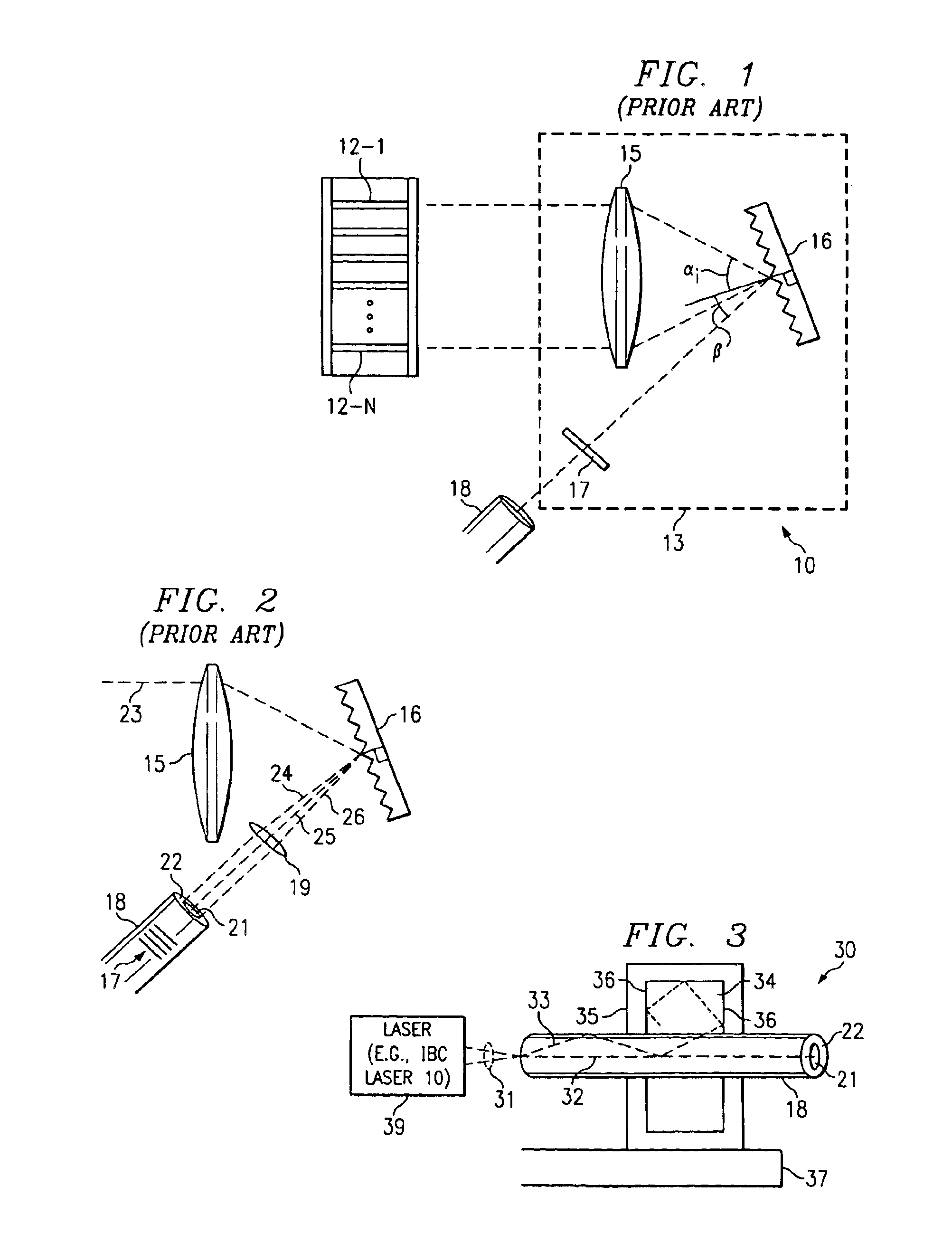
prior art;

[0013]FIG. 2 depicts a single beam processed by an incoherently beam combined laser according to the prior art; and

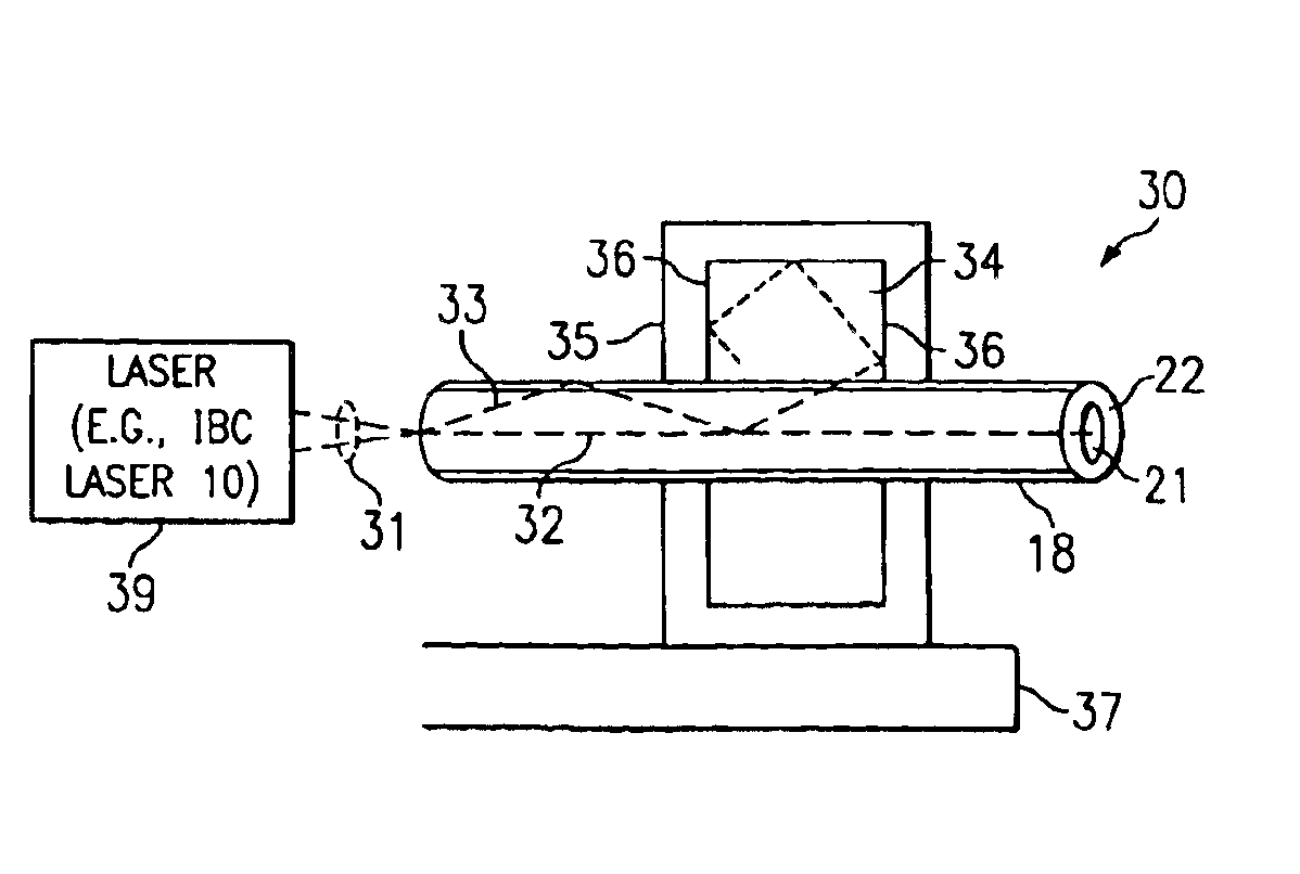
[0014]FIG. 3 depicts a system for dissipating cladding modes of a laser according to embodiments of the present invention.

DETAILED DESCRIPTION OF THE INVENTION

[0015]Before discussing the present invention in greater detail, it is appropriate to discuss the physical characteristics of IBC laser technology that may become problematic when relatively higher output powers are utilized. FIG. 2 depicts a portion of an IBC laser. It shall be appreciated that FIG. 2 is not drawn to scale or drawn according to an actual geometry for the purpose of illustrating the respective elements conveniently for the reader. The IBC laser generates beam 23 from one of its emitters 12-1 through 12-N (which are not shown in FIG. 2). Beam 23 may comprise several closely spaced Fabry-Perot modes. Accordingly, beam 23 does not consist of essentially one wavelength. It shall be appreciat...


PUM


Abstract

An embodiment is directed to a system for dissipating cladding modes of an optical fiber. In the system, a high power light source couples optical power into the optical fiber at a fiber coupling point thereby producing the cladding modes; material is indexed-matched to the optical fiber and is optically contacted to the optical fiber near the fiber coupling point; and a substrate layer is operable to provide a thermal sink for heat generated from dissipation of cladding modes of the optical fiber.

Description

TECHNICAL FIELD[0002]The present invention is related to operation of fiber optical devices and, more particularly, to operation of low coupling efficiency devices by dissipating cladding modes.BACKGROUND OF THE INVENTION[0003]Incoherently beam combined (IBC) lasers combine the output from an array of gain elements or emitters (typically consisting of semiconductor material, such as GaAlAs, InP, GaAs, InGaAs, InGaAsP, AlGaInAs, and / or the like, which is capable of lasing at particular wavelengths) into a single output beam that may be coupled into, for example, an optical fiber. The gain elements may be discrete devices or may be included on an integrated device. Due to the geometry of IBC lasers, each gain element tends to lase at a unique wavelength. Exemplary arrangements of IBC lasers are described in U.S. Pat. No. 6,052,394 and U.S. Pat. No. 6,192,062.[0004]FIG. 1 depicts a prior art arrangement of components in IBC laser 10. IBC laser 10 includes emitters 12-1 through 12-N whi...

Claims


Application Information

Patent Timeline
Patent Type & Authority Patents(United States)
IPC IPC(8): G02B6/42G02B6/28
CPCG02B6/4296G02B6/2852G02B6/4269G02B6/429
Inventor PRATT, MARK R.
Owner NLIGHT INC
Why Eureka
Try Eureka