Open Frame Electronic Chassis For Enclosed Modules

a technology of electronic chassis and enclosed modules, which is applied in the field of passive cooling modular electronic systems having an openframe chassis, can solve the problems of other components failing, forced air cooling modular electronic systems not operating well in harsh environments, and electrical components in the modules tending to generate large amounts of heat, so as to reduce the cost, reduce the mean time between failures of the modules, and reduce the generated heat

Active Publication Date: 2010-11-18
SIEMENS CANADA LTD
View PDF19 Cites 25 Cited by
  • Summary
  • Abstract
  • Description
  • Claims
  • Application Information

AI Technical Summary

Benefits of technology

[0013]In another aspect of the present invention, the modules fully enclose their electrical components such that no ambient air can enter into the modules. Rather, internal conductive surfaces spread and transfer heat to the heat sink area of the module which in a preferred embodiment comprises die cast integrated heat fins. In this way, heat generated by the electrical devices can be directed within the modules towards the heat sink area to dissipate the generated heat in a controlled manner. Furthermore, because the modules are completely enclosed, there is no concern of dirt or dust coming into contact with the electrical components contained in the module thereby increasing the mean time between failures of the modules.
[0014]In a further preferred embodiment, the modules are all of the same shape and size. This decreases the cost associated with manufacturing the modules. Preferably the modules are made of aluminum to provide a module of reasonable weight, and also improve heat transfer abilities. It is understood that any material which is a relatively good conductor of heat would preferably be used as the casing for the modules.
[0015]In a further aspect of the invention, the modules preferably have unique key housing for each type of module. The key housing of the modules preferably have key holes which mate with key pins on the back plane of the chassis, which key pins are oriented in different positions so that each type of module can be connected only to the corresponding type of chassis electrical connection in the back plane. In this way, the correct type of module will be inserted into the correct slot in order to avoid damaging the electrical connections on the module and the back plane. Preferably, the key pins extend from the back plane a greater distance than the electrical connections, to ensure that the key pins engage the module key housing before the electrical connections meet, thereby avoiding the possibility of damaging the electrical connections in the module and back plane. The key pins are also selected in the back plane such that, even if an incorrect module is inserted into the slot, the key pins will not contact the electrical connection on the module, but rather will contact a flat surface area so as not to damage any electrical connections on the module.
[0016]In another aspect of the invention, the modules have guide pins or alignment pins to decrease vibration and shock to the module, and more particularly, the electrical components contained therein. The module guide pins engage corresponding alignment holes in the chassis to secure the module to the chassis.
[0017]In a further aspect of the present invention, the modules have rails which extend along the length of the module in an insertion direction and engage channels in the open frame chassis. The channels may extend across the bottom opening and / or top opening, but are preferably narrow to avoid excess interference with the ambient air flow through the top and bottom openings. During insertion, the rail on the module engages the channel and is slid along the channel in an insertion direction until the module is at the inserted position. Preferably, the rails are located remotely from the heat sink area so that the channel and rail do not impede ambient air flow across the heat sink area when the module is in the inserted position. In a preferred embodiment, the heat sink area extends along a first side wall of the module and the rail extends along the bottom of the module adjacent a second side wall of the module opposed to the first side wall.

Problems solved by technology

However, the electrical components in the modules tend to generate large amounts of heat when they are in use.
However, the forced-air cooled modular electronic systems do not operate well in harsh environments for a number of reasons.
First, in harsh environmental conditions, it is not always possible to have the fan operational and a fan failure may not become immediately apparent, which may cause other components to fail before the fan failure is noticed.
Second, in harsh environmental conditions, which tend to also be dirty conditions, the air generally has dust and other airborne contaminants contained therein, such that perpetually forcing air around delicate electronic components may eventually cause undesired failures decreasing the “Mean Time between Failures” (MTBF) of the modules.
However, because conduction cooled enclosed chassis are enclosed, they are not modular and do not permit reconfiguration of the systems by the exchange of modules therein.
Furthermore, such conduction cooled enclosed chassis must be entirely replaced even if a single component fails.
As a result, such conduction cooled enclosed chassis give rise to maintenance and replacement issues in the field, which cause Mean Time to Repair (MTTR) to decrease.
An acute shock, or prolonged vibration, may lead to failure of highly sensitive electronic devices thereby also decreasing the mean time between failures (MTBF).

Method used


Image

  • Open Frame Electronic Chassis For Enclosed Modules
  • Open Frame Electronic Chassis For Enclosed Modules
  • Open Frame Electronic Chassis For Enclosed Modules

Examples


Embodiment Construction

[0034]Preferred embodiments of the invention and its advantages can be understood by referring to the present drawings. In the present drawings, like numerals are used for like and corresponding parts of the accompanying drawings.

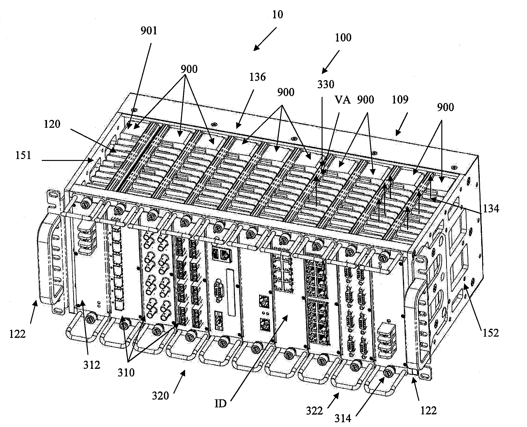
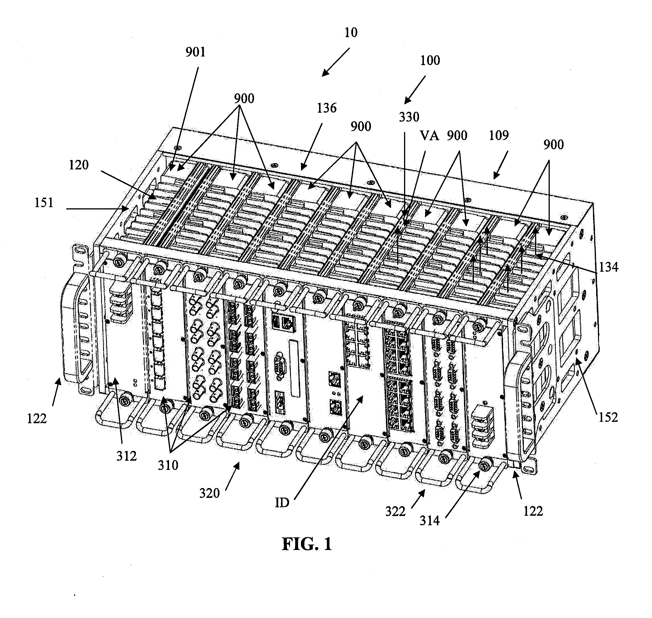
[0035]As shown in FIGS. 1 and 3 to 6, one embodiment of the present invention provides a passively cooled module electronic system, as shown generally by reference numeral 10. The passively cooled modular electronic system 10 comprises an open frame chassis, as shown generally by reference numeral 100, and at least one and preferably a plurality of modules 900. While FIG. 1 shows modules in all of the slots 163 of the open frame chassis, it is understood that modules 900 may only be present in some of the slots 163.

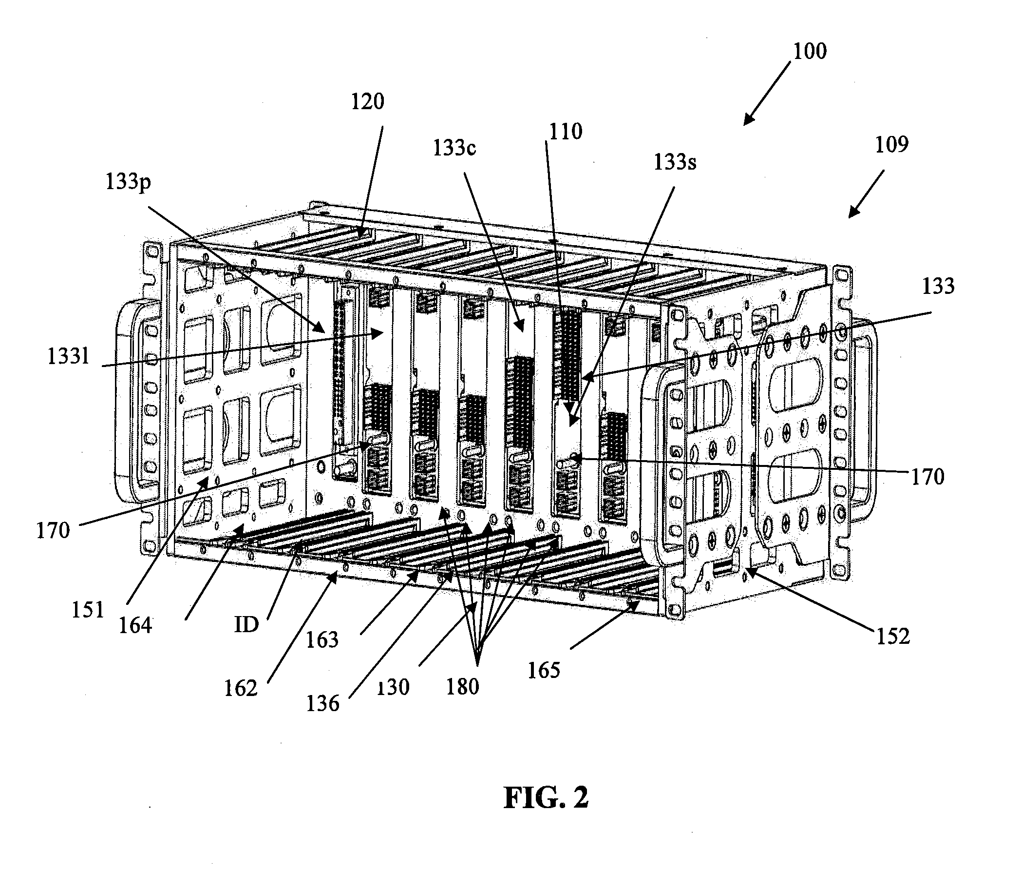
[0036]The open frame chassis 100 is better shown in FIG. 2 where all the modules 900 have been removed from the slots 163. As illustrated in FIG. 2, the open frame chassis 100 comprises a bottom opening 130 and a top opening 120. It is understood...


PUM


Abstract

An open frame chassis has a top opening and a bottom opening permitting ambient air flow there through. A plurality of modules, each enclosing electrical components which are in thermal contact with a heat sink area of their corresponding module, and each of which can be inserted to an inserted position in the open frame chassis. When the modules are inserted into the open frame chassis, ambient air may flow from the bottom opening of the chassis across the heat sink area of each module to the top opening in order to passively cool the modules and the electrical components enclosed therein. The heat sink area has fins which are separated by a distance of 9 mm to 12 mm and have a height 10 mm to 20 mm. Key pins are associated with the electrical connectors of the chassis to guide the modules into place and prevent incorrect insertion of a different type of electrical module not corresponding to the electrical connection of the chassis for that slot. Guide pins are present on the corners of the modules to mate with guide holes in the chassis to secure the module to the open frame chassis and decrease vibration. Both sides of the chassis have side openings through which the fins of the modules inserted into the end slots of the chassis may be exposed. The power modules are inserted into the end slots. The chassis has an inverted connection at one end slot to accommodate identical power modules at both end slots such that the heat sink area always faces a side opening in the open frame chassis.

Description

CROSS REFERENCE TO RELATED APPLICATION[0001]This application claims the benefit of Canadian Application No. (yet to be administered), filed May 15, 2009.FIELD OF THE INVENTION[0002]This invention relates to modular electronic systems having a chassis and modules that are hot-swappable. More particularly, the present invention relates to a passively cooled modular electronic system having an open-frame chassis permitting air flow around and through a plurality of modules each module encasing heat generating electrical devices therein.BACKGROUND OF THE INVENTION[0003]In the past, there have been many different types of modular electronic systems having a chassis with a variety of modules that can be interconnected to the back plane of the chassis. However, the electrical components in the modules tend to generate large amounts of heat when they are in use. Therefore, to accommodate the heat generated by the electrical components these conventional electronic systems generally use fans...

Claims


Application Information

Patent Timeline
Patent Type & Authority Applications(United States)
IPC IPC(8): H05K7/20
CPCH05K7/20545
Inventor ZENG, GUANGMOORE, ROGERLEVY, PHILLUSKIND, YURI
Owner SIEMENS CANADA LTD
Why Eureka
Try Eureka