Heat conducting seal

a heat conducting seal and shaft technology, applied in the direction of positive displacement liquid engines, piston pumps, liquid fuel engines, etc., can solve the problems of reducing the chance of seal failure, and achieve the effect of dissipating frictional heat, dissipating extra generated heat, and reducing the chance of impeller and/or pump failur

Active Publication Date: 2006-06-08
FREUDENBERG NOK GEN PARTNERSHIP
View PDF12 Cites 4 Cited by
  • Summary
  • Abstract
  • Description
  • Claims
  • Application Information

AI Technical Summary

Benefits of technology

[0006] An advantage of the present invention is that a seal seat assembly can dissipate frictional heat generated during dry pump operation, thus significantly reducing the chance of impeller and / or pump failure. In a dishwashing machine, for example, if the dishwasher is run without the water supply valve open, then one will have dry pump operation. The seal seat assembly dissipates extra generated heat, thus significantly reducing the chances of seal damage that can lead to pump failure and later water leakage.
[0007] Another advantage of the present invention is that a washer mounted adjacent a motor shaft sleeve or shoulder will allow the impeller to be augered onto the shaft while preventing it from being augered on too far. This significantly reduces the chances of a seal failure due to augering of the impeller too far onto the shaft.
[0008] Further areas of applicability of the present invention will become apparent from the detailed description provided hereinafter. It should be understood that the detailed description and specific examples, while indicating the preferred embodiment of the invention, are intended for purposes of illustration only and are not intended to limit the scope of the invention.

Problems solved by technology

This significantly reduces the chances of a seal failure due to augering of the impeller too far onto the shaft.

Method used


Image

  • Heat conducting seal
  • Heat conducting seal

Examples


Embodiment Construction

[0011] The following description of the preferred embodiment(s) is merely exemplary in nature and is in no way intended to limit the invention, its application, or uses.

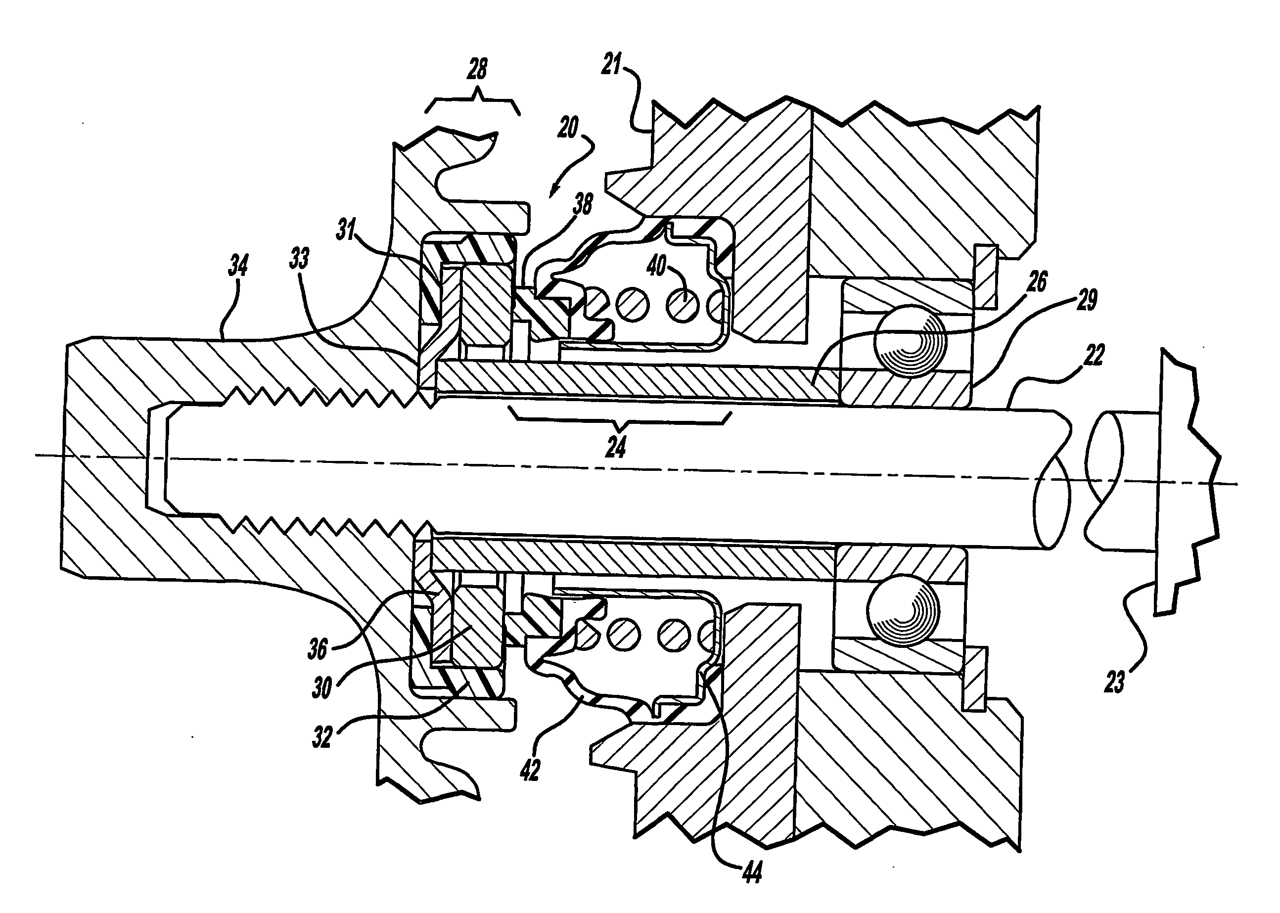
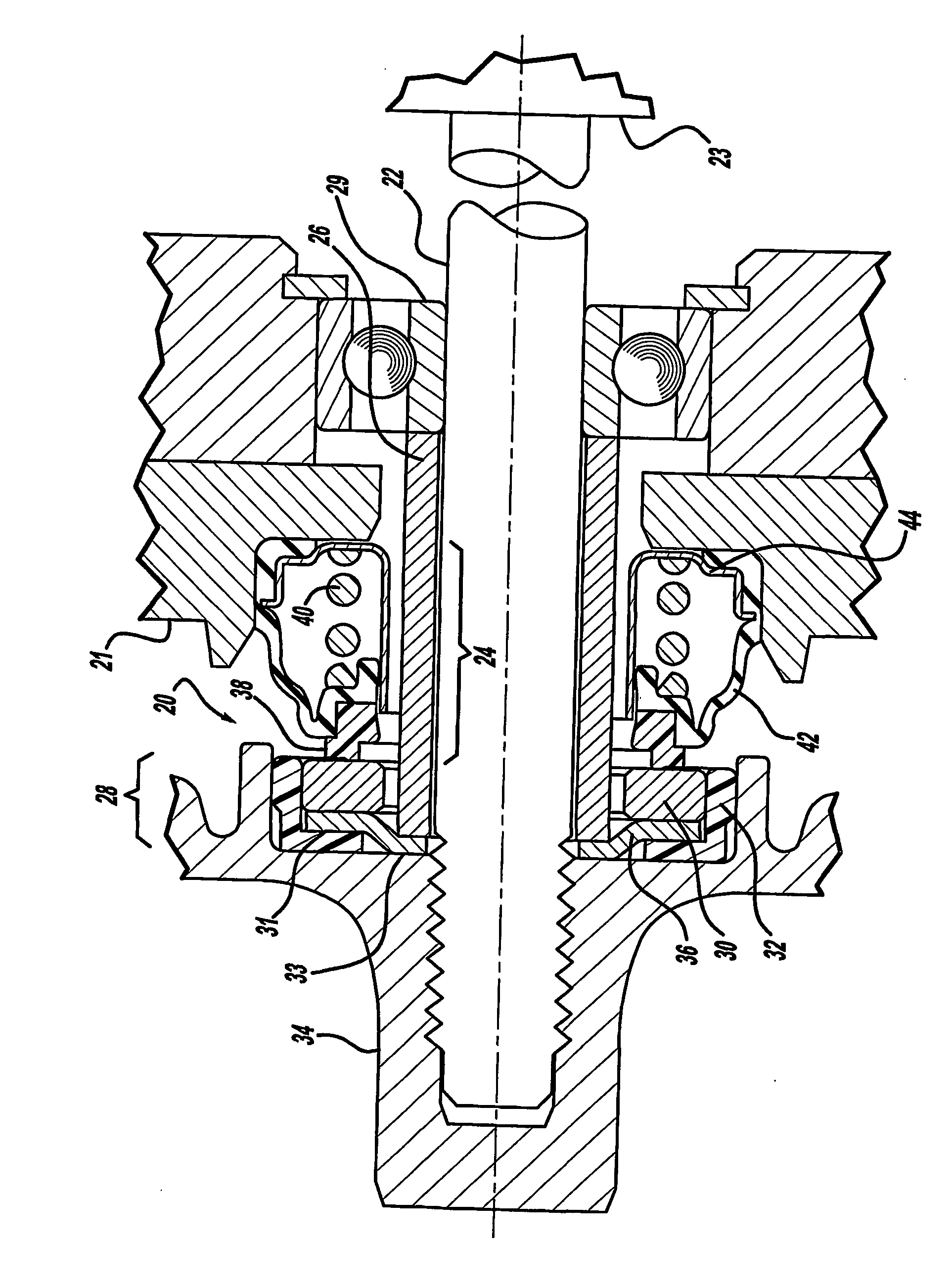
[0012] The drawing illustrates a mechanical face seal assembly 20 mounted about a rotatable shaft 22. The rotatable shaft 22 may be driven by, for example, a pump motor 23 in an automatic dishwasher—although, the seal assembly 20 may be employed in other types of sealing applications for a rotatable shaft 22. The shaft 22 includes a shaft sleeve 26 mounted thereon. As an alternative to a shaft sleeve, the shaft 22 may have a shoulder formed thereon.

[0013] The seal assembly 20 includes a seal head assembly 24, mounted stationary relative to a pump housing 21, and a heat conducting seal seat assembly 28, rotationally fixed to the shaft 22. A bearing 29 mounts on the shaft 22, with an inner race thereof abutting the shaft sleeve 26.

[0014] The heat conducting seal seat assembly 28 includes a seal seat 30, which abuts ...


PUM


Abstract

A mechanical face seal, for sealing about a rotating shaft, includes a seal head assembly in sealing engagement with a seal seat assembly. The seal seat assembly has a washer with a portion that is sandwiched between a grommet and a seal seat. Another portion of the washer is sandwiched between a sleeve or shoulder on the shaft and an impeller. Frictional heat generated by the seal can be conducted away from the seal seat to the sleeve or shoulder on the shaft, which is particularly advantageous when the face seal is operated without water adjacent to the seal seat.

Description

CROSS-REFERENCE TO RELATED APPLICATIONS [0001] This application claims the benefit of U.S. Provisional Application No. 60 / 441,371, filed on Jan. 20, 2003. The disclosure of the above application is incorporated herein by reference.FIELD OF THE INVENTION [0002] The present invention relates in general to shaft seals, and more particularly to mechanical face seals employed with rotating shafts. BACKGROUND OF THE INVENTION [0003] A mechanical face seal, which may be employed for example in a dishwasher, may include a stationary seal head assembly that mates with and seals against a rotating seal seat assembly. Typically, the seal seat assembly mounts to an impeller that is driven, via a shaft, by a pump. It is common for the impeller to be made of a plastic material. Such a conventional face seal assembly performs very well at sealing out water, and prevents the impeller from overheating because the water adjacent to the seal absorbs frictional heat generated by the seal. A concern ari...

Claims


Application Information

Patent Timeline
Patent Type & Authority Applications(United States)
IPC IPC(8): F04B17/00F04B35/04F16J15/34F16J15/36
CPCF04D29/126F04D29/588F04D29/628F16J15/3404F16J15/36
Inventor DAHLHEIMER, JOHN
Owner FREUDENBERG NOK GEN PARTNERSHIP
Why Eureka
Try Eureka