Thermal degradation and crack resistant functionally graded cemented tungsten carbide and polycrystalline diamond

a cemented tungsten carbide and functional grade technology, applied in the field of thermal degradation and crack resistance functional graded cemented tungsten carbide and polycrystalline diamond, can solve the problems of limiting the effectiveness of some potential applications, low fracture toughness of materials, and easy cracking of materials, so as to improve the thermal conductivity of materials, avoid heat cracking and/or thermal fatigue, easy to dissipate frictional heat

Inactive Publication Date: 2009-09-10
UNIV OF UTAH RES FOUND
View PDF25 Cites 20 Cited by
  • Summary
  • Abstract
  • Description
  • Claims
  • Application Information

AI Technical Summary

Benefits of technology

[0013]The present invention is designed to provide a new type of cemented tungsten carbide (or polycrystalline diamond) material that will address the above-mentioned problems associated with heat checking or thermal fatigue cracks. This new material will be designed by having a gradient in the grain size of the particles. Specifically, top layer (or layers) of the material will have coarser grain sizes whereas the inner layers will have finer grain sizes. This means that the size of the particles at the material's top layer is larger than the size of the particles in the inner layer(s) of the material. In many embodiments, there will be a gradient in the particle size, meaning that the particle size will gradually decrease from the larger, coarser grains at the top layer to the smaller, finer grains in the inner layer(s). (The inner layer(s) may also be referred to as the “bulk substrate”). The top layer with the coarser grain sizes essentially acts as a coating for the material. The top layer, with the coarser grain sizes, increases the thermal conductivity of the material, thereby allowing the material to more easily dissipate the frictional heat caused during use of the tool. Thus, the material is well-suited to avoid heat cracking and / or thermal fatigue. At the same time, the finer grain-sized particles throughout the inner layers of the material impart a sufficient hardness and wear resistance to the material. Accordingly, the materials of the present embodiments have the desired properties, namely high strength and wear resistance, and at the same time, resist heat cracking and / or thermal fatigue.

Problems solved by technology

However, cemented tungsten carbide materials have been known to more easily fracture than steel.
Many WC—Co materials have a relatively low fracture toughness which limits their effectiveness in some potential applications.
This low fracture toughness means that the material has a propensity to chip or fracture during use.
Chipping and fracturing are the leading causes of degradation or premature failure or cemented tungsten carbide tools.
At the same time, many PCD materials suffer from many of the same deficiencies as WC—Co materials.
As noted above, one of the common modes of failure of tools made of WC—Co and / or PCD materials is that they tend to crack, chip, or fracture during use.
Such cracking or failure of these materials is especially common when the tool become hot (as a result of the friction caused by contact with another surface).
This increase in temperature is due to intense frictional heating.
When the thermal conductivity of the tool is “low,” the temperature of the cutting area will be higher because the tool is not able to dissipate the heat away from the cutting area.
Then, when a coolant or cooling system is used, the cutting tool may experience drastic and sudden changes in temperature, namely, sudden heating caused by the frictional contact and then sudden cooling caused by the cooling system.
These sudden changes in temperature may cause the thermal fatigue and thermal cracking of the tool.
Accordingly, the high temperature associated with tool usage also creates cyclic residual stresses between the hard particles and matrix phase.
Such cyclic residual stresses can be an additional cause of heat checking cracks (thermal fatigue) of the material.
Of course, heat-checking cracks in a tool surface can propagate and get larger over time.
When such cracks exceed a “critical size,” the tool can no longer be safely used.
At this time, the tool must be replaced and discarded, thereby increasing the overall costs of the cutting process.

Method used


Image

  • Thermal degradation and crack resistant functionally graded cemented tungsten carbide and polycrystalline diamond
  • Thermal degradation and crack resistant functionally graded cemented tungsten carbide and polycrystalline diamond
  • Thermal degradation and crack resistant functionally graded cemented tungsten carbide and polycrystalline diamond

Examples


Embodiment Construction

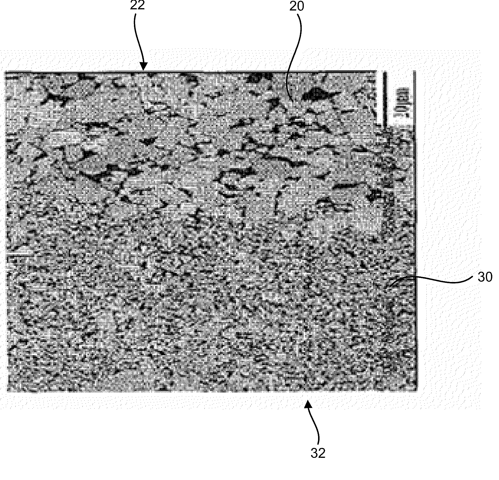
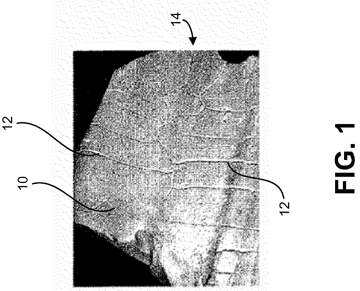
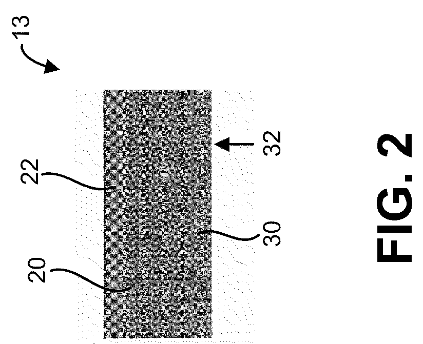
[0018]The embodiments of the present invention will be best understood by reference to the drawings, wherein like parts are designated by like numerals throughout. It will be readily understood that the components of the present invention, as generally described and illustrated in the figures herein, could be arranged and designed in a wide variety of different configurations. Thus, the following more detailed description of the embodiments of the present invention, as represented in the Figures, is not intended to limit the scope of the invention, as claimed, but is merely representative of embodiments of the invention.

[0019]The present embodiments involves the understanding of how the conductivity and mechanical properties of WC—Co and PCD materials may be affected by the composition (i.e., amount of cobalt) and the microstructure (i.e., the grain size of the particles) of the material. This relationship is described herein.

[0020]The thermal conductivity of WC—Co or polycrystallin...


PUM

PropertyMeasurementUnit
sizeaaaaaaaaaa
sizeaaaaaaaaaa
thicknessaaaaaaaaaa

Abstract

A WC—Co material or polycrystalline diamond-Co material that has a gradient in the grain size of the particles. Specifically, the material may have a top layer that has coarse grains that is designed to dissipate the heat caused by friction (and thus prevent thermal cracking). The material will then have a bulk substrate that is made up of finer grains and provide adequate hardness for the material. The top layer is positioned on top of the bulk substrate.

Description

CROSS-REFERENCE TO RELATED APPLICATIONS[0001]This application claims the benefit of U.S. Provisional Patent Application No. 61 / 034,842 filed on Mar. 7, 2008. This application is expressly incorporated herein by reference.BACKGROUND OF THE INVENTION[0002]Cemented tungsten carbide materials are known in the industry. This material constitutes a composite material of tungsten carbide (WC) that is embedded in a cobalt matrix. (Cemented tungsten carbide materials are sometimes abbreviated as “WC—Co”.) Typical compositions of the cobalt metal ranges from 3 to 30 percent by weight, although other percentages of cobalt may be used. For background information regarding cemented tungsten carbide materials, the reader is invited to consult U.S. Patent Application Publication No. 2005 / 0276717 A1 (which publication is expressly incorporated herein by reference).[0003]Cemented tungsten carbide materials have unique properties compared to steel, metal alloys, or ceramic materials. For example ceme...

Claims


Application Information

Patent Timeline
Patent Type & Authority Applications(United States)
IPC IPC(8): B32B7/02B32B37/02B05D3/02
CPCB22F7/02B22F7/06B22F2999/00C22C26/00C22C29/08Y10T428/30Y10T428/24992Y10T428/24942B22F2207/13
Inventor FANG, ZHIGANG ZAK
Owner UNIV OF UTAH RES FOUND
Why Eureka
Try Eureka