Heat radiating structure for electronic module and electronic device having the same

a technology of electronic modules and heat radiating structures, which is applied in the direction of electrical equipment, electrical apparatus, electrical apparatus contruction details, etc., can solve the problems of heat release, difficult to dissipate generated high temperature to the outside of the cell phone, and the electronic devices also have been getting smaller and light-weight, so as to achieve the effect of dissipating generated hea

Inactive Publication Date: 2009-07-23
SAMSUNG ELECTRONICS CO LTD
View PDF19 Cites 4 Cited by
  • Summary
  • Abstract
  • Description
  • Claims
  • Application Information

AI Technical Summary

Benefits of technology

[0037]According to the present invention, the heat radiating structure for an electronic module may include a heat radiating sheet comprised of a plurality of the heat conductive sheets. Using the heat radiating structure for an electronic module in accordance with the present invention makes it possible not only to perform the heat release function but also to correspond with the trends for the minimization of the size and the weight.
[0038]Since the heat radiating structure for an electronic module of the present invention is formed without the heat insulating plate of the prior art, it is possible to solve the problems with the partial temperature differences caused by the heat insulating plate, and the other points at issue in advance.
[0039]Furthermore, the heat radiating structure for an electronic module according to the present invention can more include impact absorbers that absorb the impacts from outside. Using the heat radiating structure for the electronic module in accordance with the present invention makes it possible not only to dissipate the generated heat from the electronic module to the outside but also to block or minimize the impact from the outside and thereby not being transferred to the electronic module by absorbing it.

Problems solved by technology

Not only are the electronic devices of excellent quality and contain more multi-function capability than ever before, but such electronic devices also have been getting smaller and light-weighted.
However the reduced size introduces problems with heat release because of the high temperature generated form the densely packed components.
When high temperature is generated from one or more of the components inside, it is very difficult to dissipate generated high temperature to the outside of the cell phone.
Especially when the electronic modules, such as a projector module, which generates lots of heat, are installed inside the cell phone and are generating a great deal of heat during operation, the heat-release problem is getting worse.
Firstly, because the heat transfer plate 31 of the heat radiating structure for an electronic module 30 show in FIG. 1 is installed on one side of the lighting unit 25, which is the heavy heat generating part, by extending from one side of the lighting unit 25 to the outside for a certain distance, there is a problem in that the heat transfer plate occupies a significant amount of space of the electronic device.
Consequently, it may cause the substrate 27 of the lighting unit 25 to bend or twist and thus adversely change the alignment of the LED 26 formed on the substrate 27.

Method used


Image

  • Heat radiating structure for electronic module and electronic device having the same
  • Heat radiating structure for electronic module and electronic device having the same
  • Heat radiating structure for electronic module and electronic device having the same

Examples


Embodiment Construction

[0048]Hereinafter, exemplary embodiments of the invention provided solely for illustrative purposes will be described in detail with reference to the accompanying drawings. A projector module will be described as an exemplary embodiment of the electronic module, and a cellular phone will be described as an exemplary embodiment of the electronic device. However, the present invention is not limited to the exemplary embodiments described herein and various changes or features may be made in the functions and arrangement of the elements that are within the spirit of the invention and the scope of the appended claims. With regard to the drawings, the same reference numerals and signs are used throughout the different drawings to designate the same or similar components.

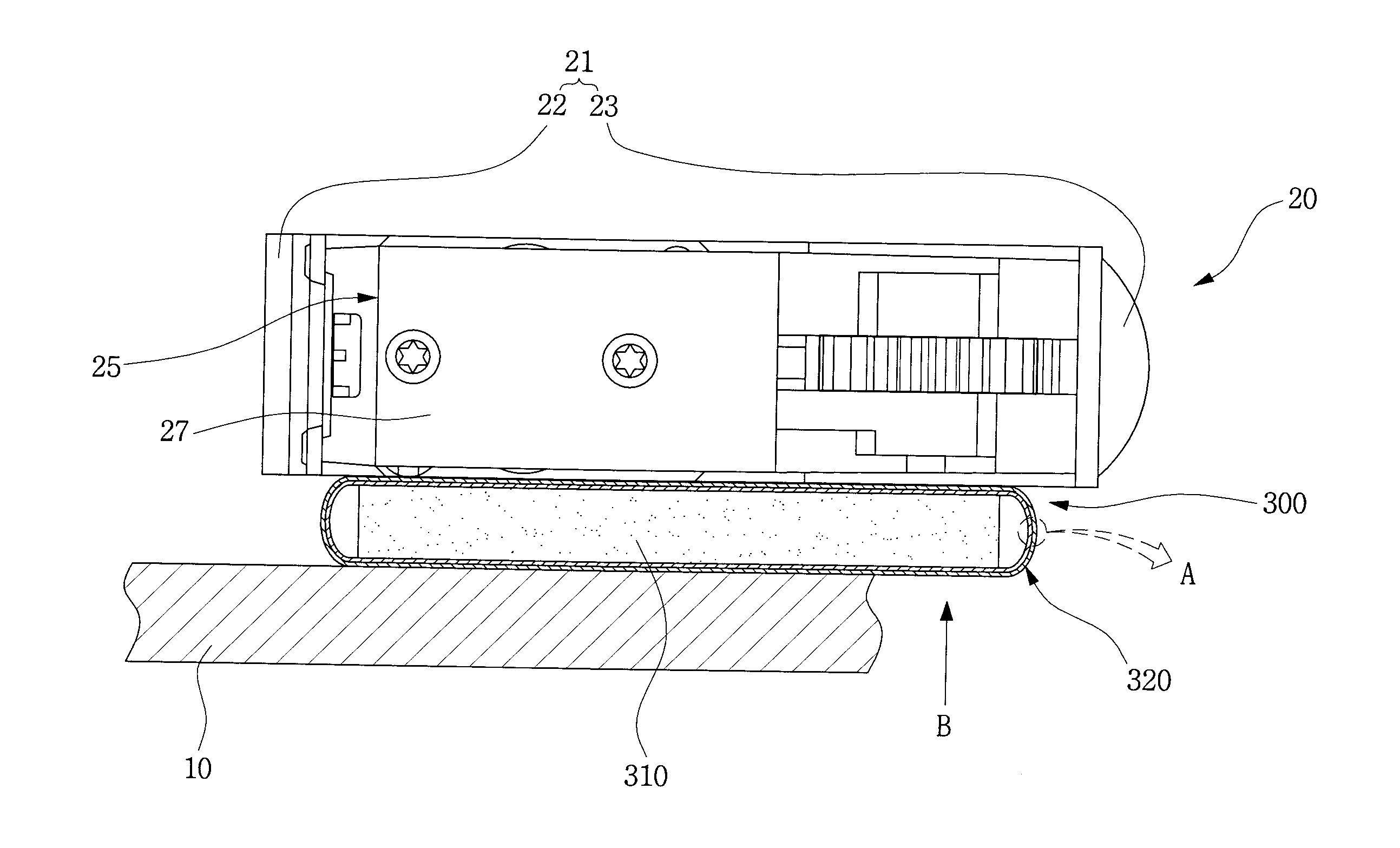
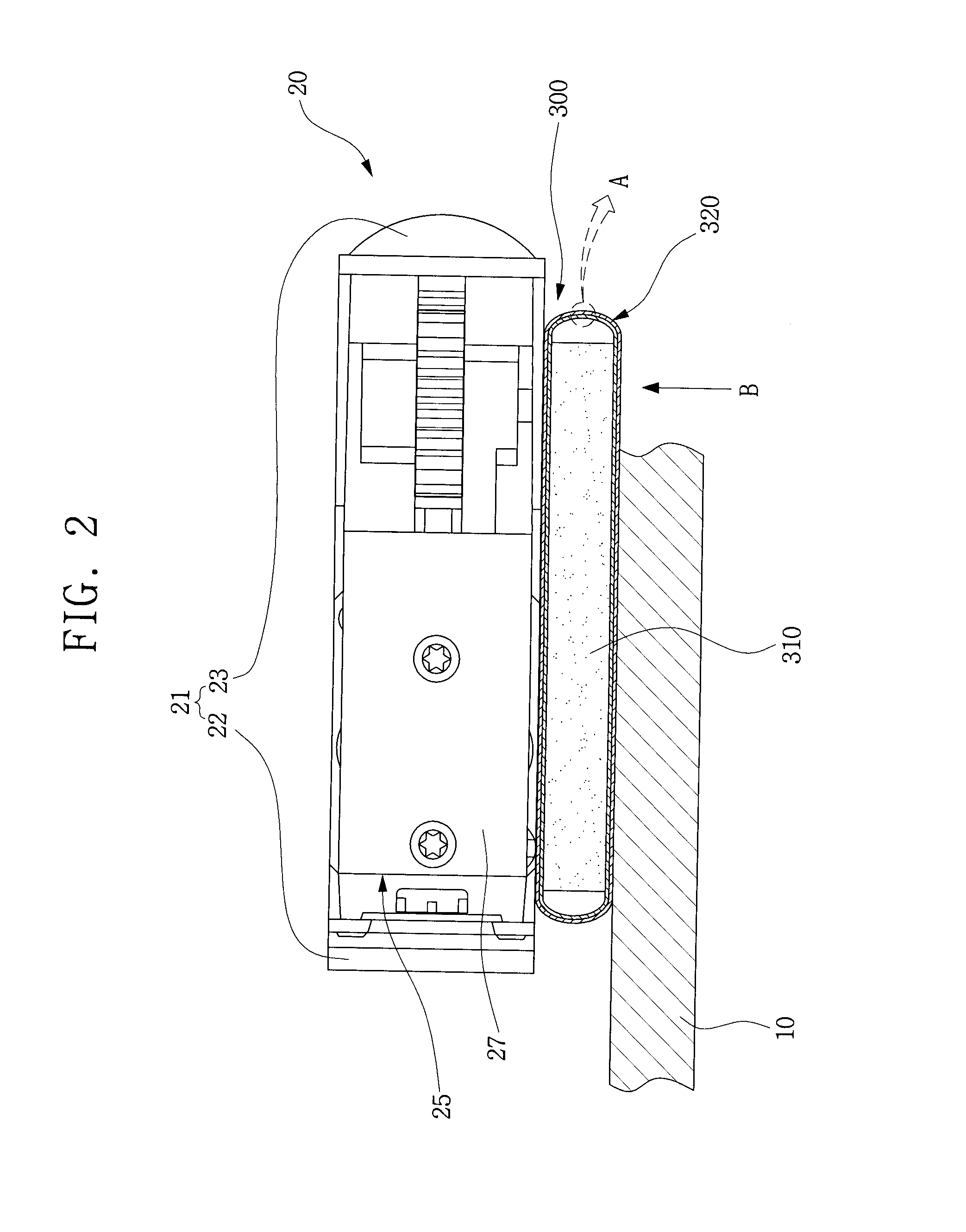
[0049]FIG. 2 is a side cross-sectional view of an electronic device having a heat radiating structure for an electronic module according to an exemplary embodiment of the present invention. FIG. 3 is a cross-sectional vie...


PUM


Abstract

A heat radiating structure for an electronic module and an electronic device having the same structure thereon. The heat radiating structure is formed at the bottom of the electronic module to release the generated heat from the electronic module, and includes an impact absorber, which absorbs impact transferred from the outside. A heat radiating sheet is formed with a plurality of the multi-layered heat conductive sheets and is in contact with the bottom of the electronic module by covering the outside of the impact absorber.

Description

CLAIM OF PRIORITY[0001]This application claims priority under 35 U.S.C. §119 from an application for “Heat Radiating Structure for Electronic Module and Electronic Device Having the Same” earlier filed in the Korean Intellectual Property Office on Jan. 17, 2008 and there duly assigned Serial No. 10-2008-0005407 and hereby incorporated by reference in its entirety.BACKGROUND OF THE INVENTION[0002]1. Field of the Invention[0003]The present invention relates to a heat radiating structure for an electronic module and an electronic device having the same. More particularly, the present invention relates to a heat radiating structure which can quickly release heat from the electronic module outside, and for an electronic device having the same structure thereon.[0004]2. Description of the Related Art[0005]In accordance with the recent development of the overall industrial technologies, multi-functional electronic devices with superb quality have been continuously introduced these days.[00...

Claims


Application Information

Patent Timeline
Patent Type & Authority Applications(United States)
IPC IPC(8): H05K7/00
CPCH05K7/20472H05K7/20
Inventor LEE, JUNG-KEEPARK, MUN-KUEHEO, DU-CHANG
Owner SAMSUNG ELECTRONICS CO LTD
Why Eureka
Try Eureka