Eureka AIR delivers breakthrough ideas for toughest innovation challenges, trusted by R&D personnel around the world.

Plastic film bag assembly and process of filling

Inactive Publication Date: 2005-04-19
PACKAGING INNOVATION
View PDF28 Cites 10 Cited by
  • Summary
  • Abstract
  • Description
  • Claims
  • Application Information

AI Technical Summary

Benefits of technology

[0007]Another object of the present invention is to provide a plastic film bag assembly wherein the bags are selectively individually fillable and dispensable quickly and efficiently and without the use of support pegs.
[0010]The present invention is further directed to a process of placing product in the plastic film bag by grasping the bag front wall and pulling the bag away from the header with a first force sufficient for severing along the tear sections and thereby severing the header inwardly from the side edges and along the severance line tear sections. Thereafter, while the bag is attached to the header at the support sections, product is placed through the bag opening and into the bag cavity. For better and more easy handling, the bag and product are preferably supported on a support structure. The bag front wall is then further pulled away from the header with a second force greater than the first force, thereby severing the header along the severance line support sections. Finally, the bag is yet further pulled with a force sufficient for severing the header along the severance line tear section between the support sections, thereby fully severing the bag from the header.

Problems solved by technology

Although the plastic film bag assemblies of the prior art are capable of being individually filled and dispensed, they are not without shortcomings and draw backs.
For example, the use of pegs for supporting the bag while filling requires the user to lift the bag in a somewhat precise manner to remove from the peg thereby decreasing efficiency and increasing the filling time.

Method used


Image

  • Plastic film bag assembly and process of filling
  • Plastic film bag assembly and process of filling
  • Plastic film bag assembly and process of filling

Examples


Embodiment Construction

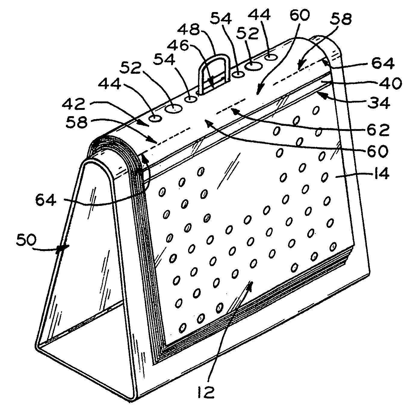
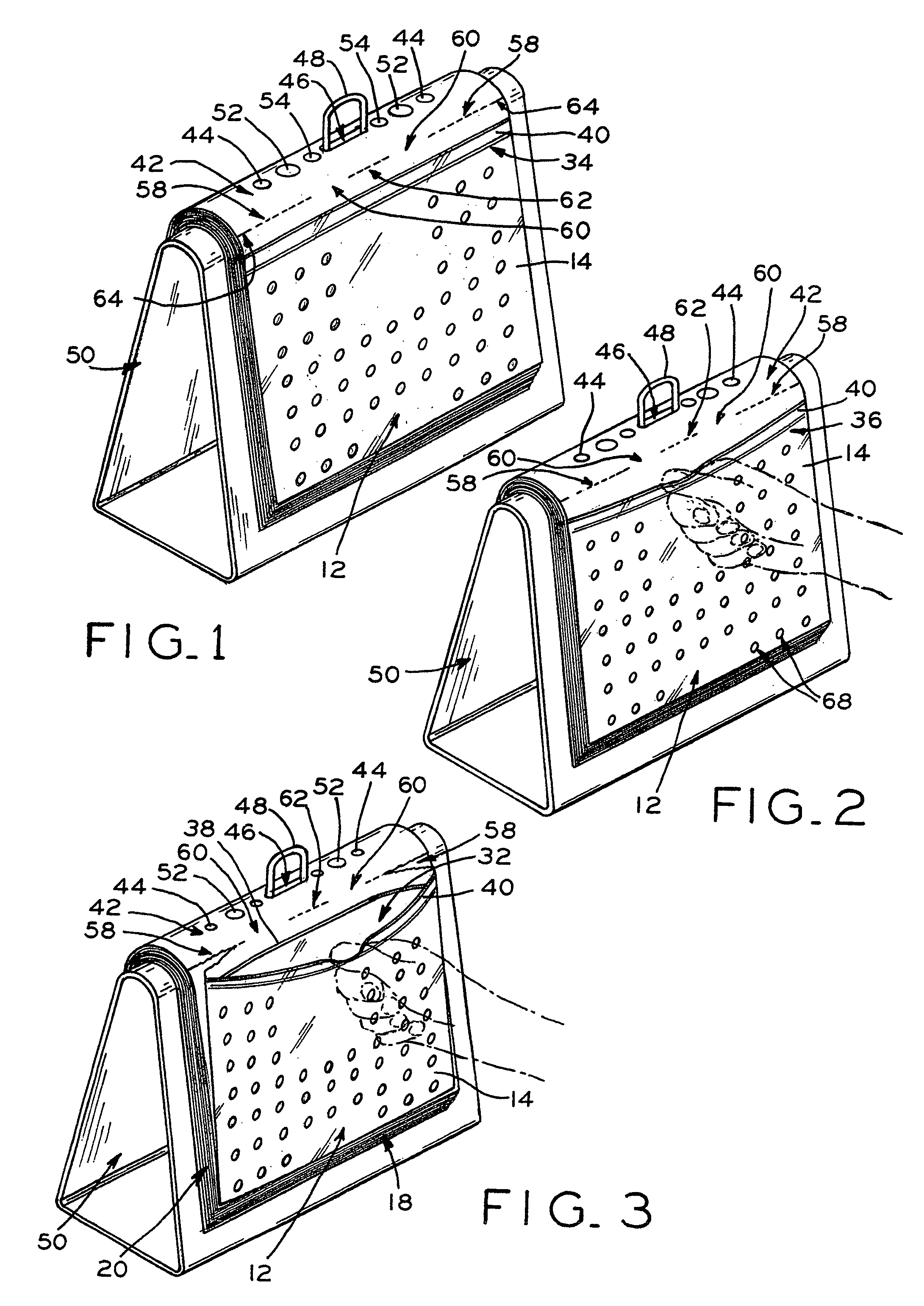
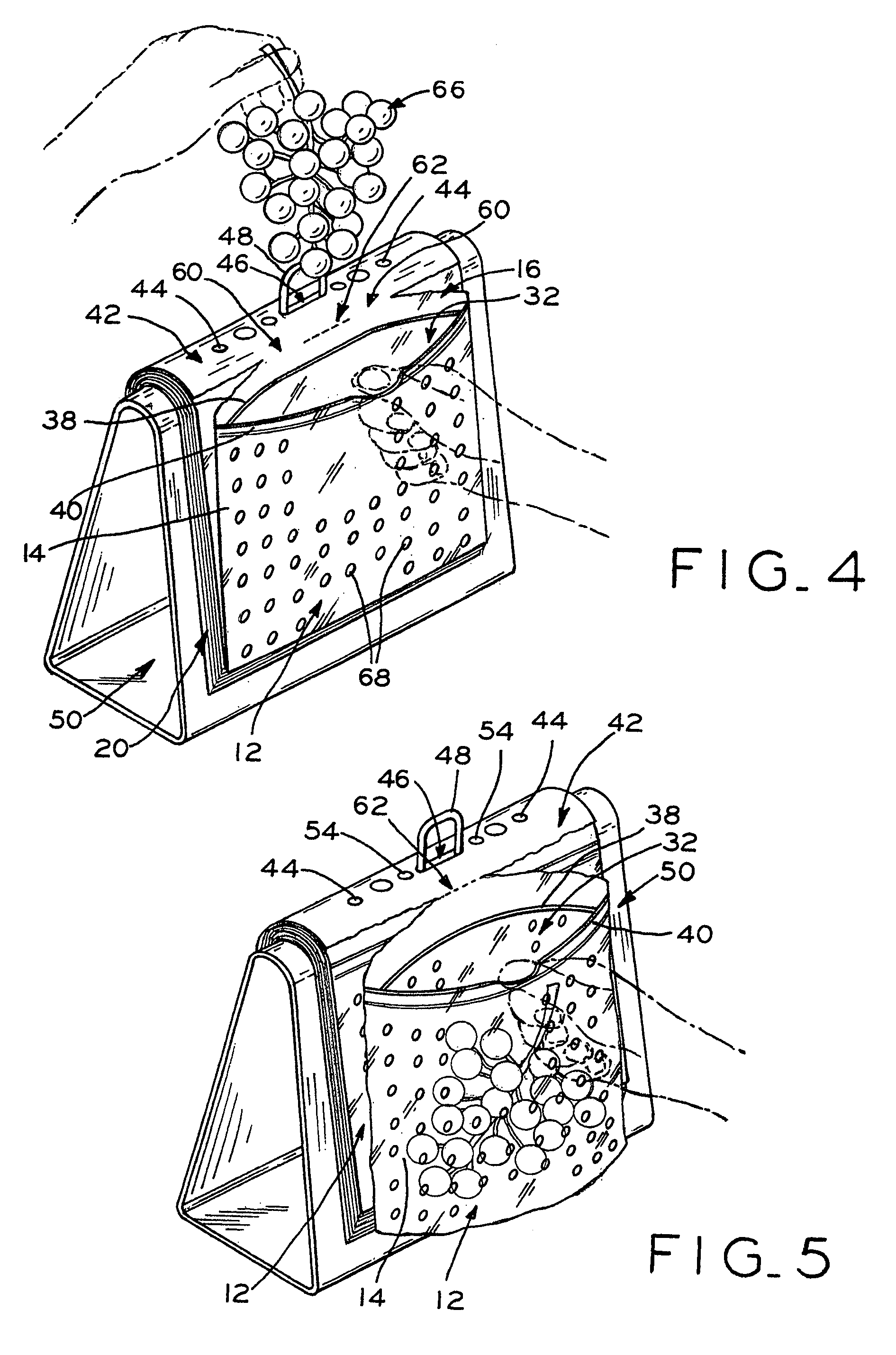
[0029]Referring initially to FIGS. 7 through 9, a plastic film bag assembly constructed in accordance with the principles of the present invention is shown and generally designated by the numeral 10. The plastic film bag assembly 10 includes a bag 12 made up of and including a front wall 14 and a back wall 16 joined together at their lower end 18, left edge 20, and right edge 22. Front and back walls 14 and 16 are joined or attached together by heat sealing or other suitable means or, depending on the manufacturing process, may be integral with one another at one or more of the edges or ends while the other edges or ends may be joined by heat sealing or suitable means. In the preferred embodiment as shown, the front and back walls 14 and 16 are joined at the left and right edges 20 and 22 by heat sealing whereas at the lower end 18 the front and back walls 14 and 16 are integral with one another. Further, a gusset 24 is provided at the bag lower end 18 by folding over sections 26 an...


PUM


Abstract

A plastic film bag assembly includes a bag having front and back walls joined together and defining an opening leading to a cavity. A header portion extends from the back wall for supporting the bag on a structure. A severance line extends across the header and includes tear sections extending inwardly from each of the header side edges. The severance line also includes support sections adjacent and inwardly of the tear sections. The support sections have a strength per unit length of severance line which is greater than the tear sections strength per unit length of severance line whereby, when severing the bag away from the header, a greater force is required for severing along the severance line support sections than the force required for severing along the tear sections. In use, the bag front wall lip is grasped and pulled away from the header for separating complementary profiles and opening the bag. The header tear sections are severed until reaching the support sections. The bag is retained open by continued pulling on the lip with a force insufficient for severing the support sections. Product is then placed in the bag and the lip is pulled with a sufficiently greater force for severing along the severance line support sections thereby severing the bag away from the header. For use in temporarily storing produce, the bags include a gusset for expansion and holes through the bag front and back walls for allowing air to enter the bag cavity.

Description

[0001]This application is a divisional application of U.S. Ser. No. 09 / 859,079 filed May 16, 2001, now U.S. Pat. No. 6,718,738, titled PLASTIC BAG ASSEMBLY AND PROCESS OF FILLING.TECHNICAL FIELD[0002]The present invention relates to plastic film bags and processes of filling the bags with product. More particularly, the present invention relates to a plastic film bag assembly and process of filling wherein the bag is severable from a header portion in a manner whereby, during severing, the bag is retained open for filling with product.BACKGROUND OF THE INVENTION[0003]Plastic film bags are today commonly and widely used in various applications from temporarily or semi-permanently storing many different products such as, for example, foods, electronic equipment, mechanical components, specimens, etc. Such bags are generally made of a thin film of plastic and range in size and holding capacity. When such bags are individually used for manually placing products or goods therein, it is d...

Claims


Application Information

Patent Timeline
IPC IPC(8): A47F13/08B65B43/44B65B61/12B65B67/04
CPCA47F13/085B65B43/44B65B61/12B65B67/04
Inventor HUSEMAN, DAVID C.
Owner PACKAGING INNOVATION
Why Eureka
Eureka Blog
Learn More