Automotive lane change aid

a technology for lane change and autos, applied in the field of object detection, can solve the problems of insufficient prior art systems in many driving conditions, vehicle drivers experiencing blind spots, and failure of departure-warning algorithms to adequately recognize lane change events

Inactive Publication Date: 2005-04-19
MAGNA ELECTRONICS
View PDF43 Cites 747 Cited by
  • Summary
  • Abstract
  • Description
  • Claims
  • Application Information

AI Technical Summary

Problems solved by technology

It is not uncommon, however, for a vehicle driver to experience blind spots due to the design of the vehicle bodywork, windows and the rearview mirror system.
They are particularly effective when the detected object is moving at a low relative velocity with reference to the detecting vehicle, since the detected object may spend long periods of time in the blind spot and the driver may lose track of surrounding objects.
However, prior art systems are inadequate in many driving conditions.
Failure to detect a marker usually means failure of the departure-warning algorithm to adequately recognize a lane change event.

Method used


Image

  • Automotive lane change aid
  • Automotive lane change aid
  • Automotive lane change aid

Examples


Embodiment Construction

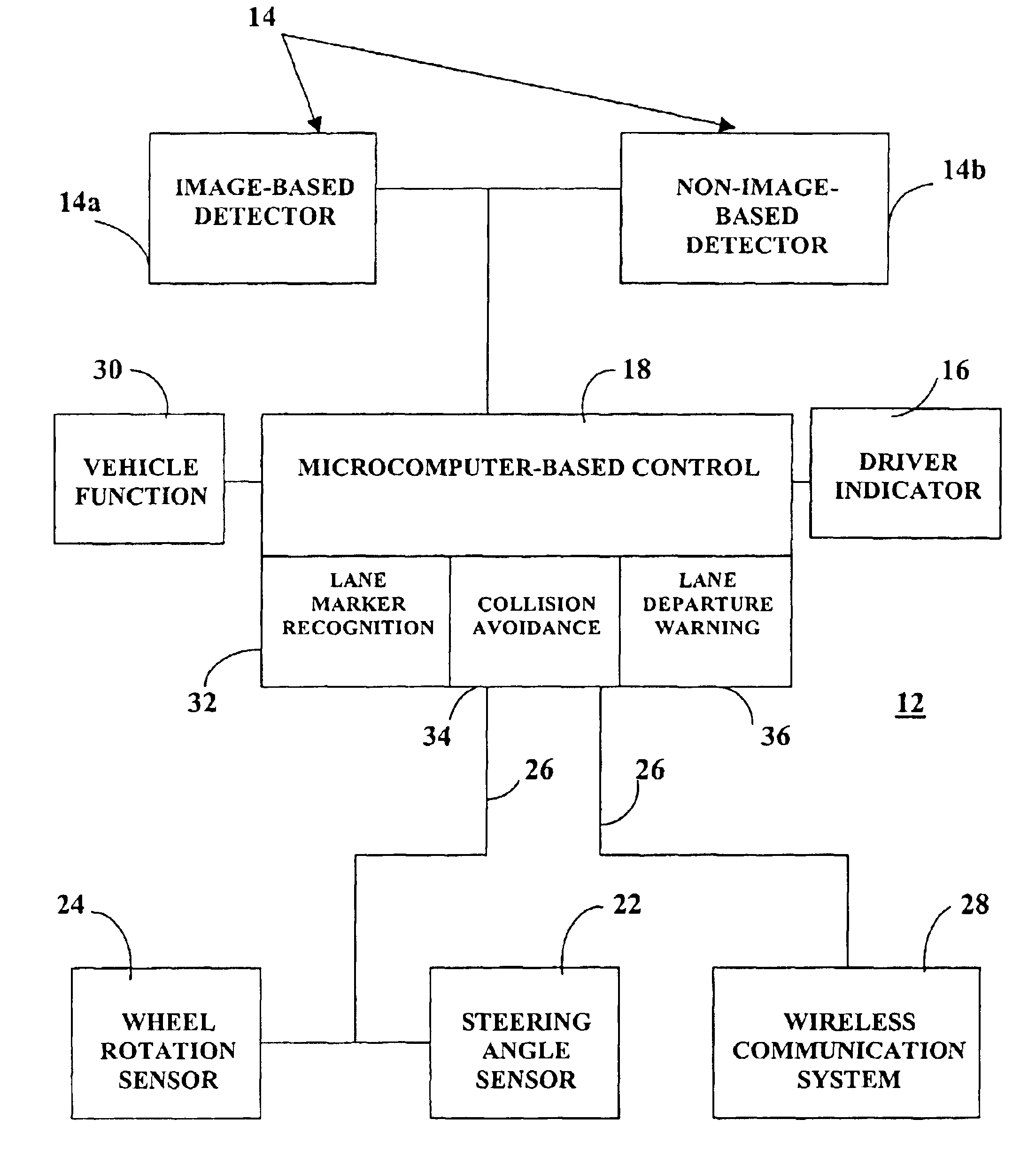
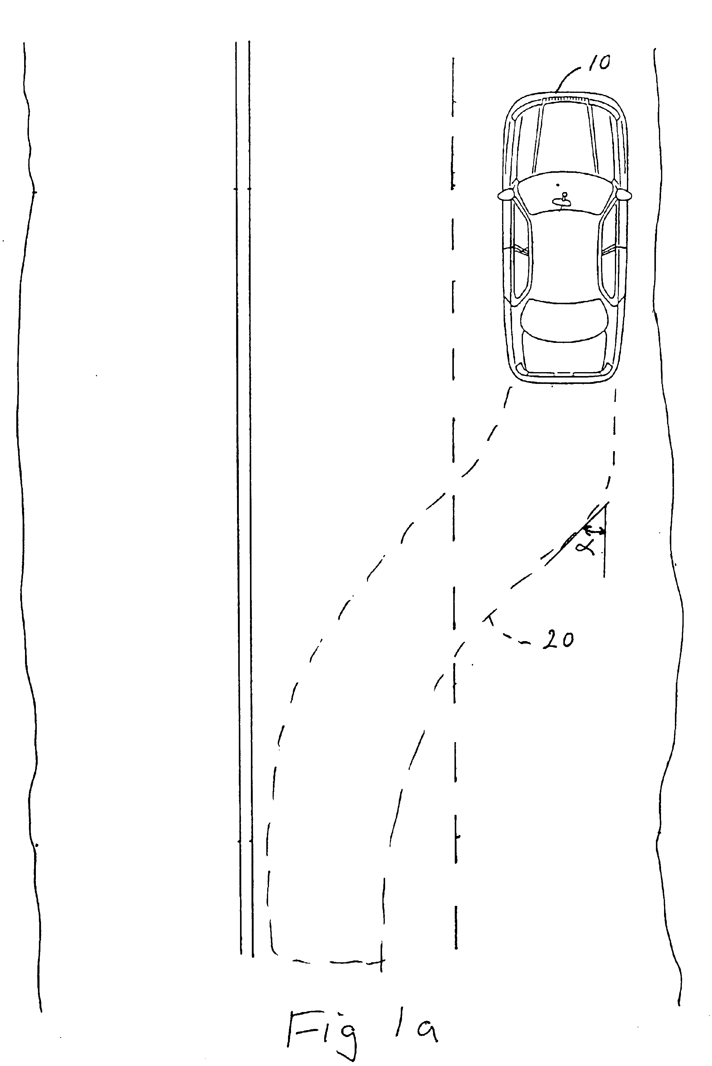
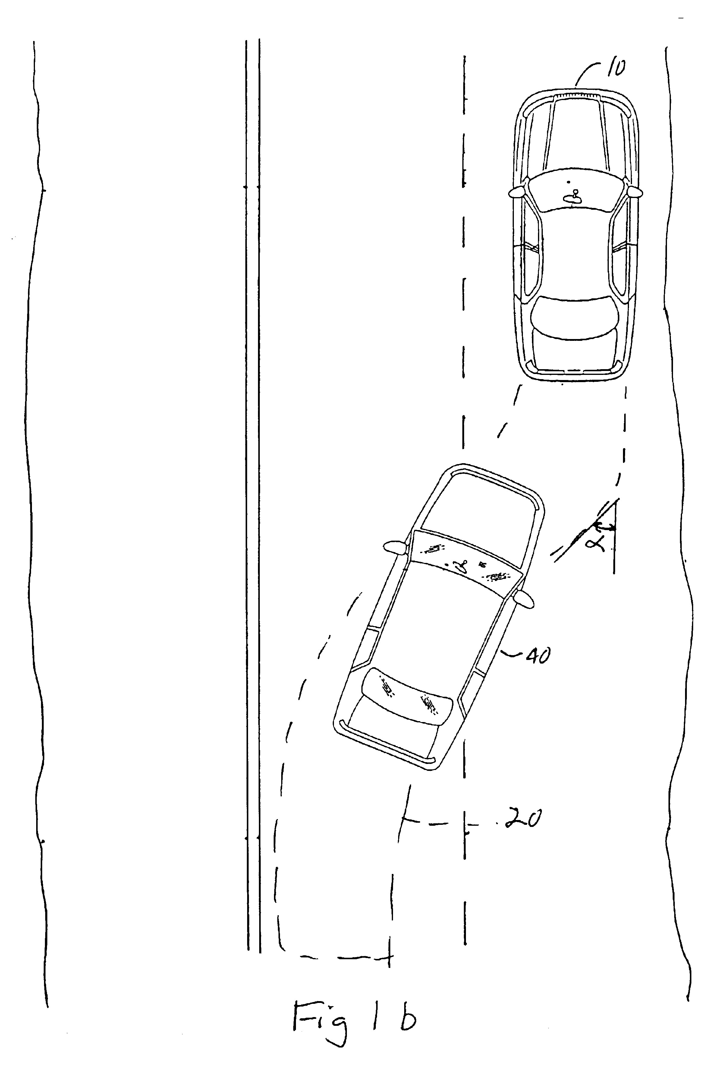
[0015]Referring to the drawings and the illustrative embodiments depicted therein, a Lane Change Aid (LCA) system 12 of the present invention as illustrated with a vehicle 10 includes a control 18 and an indicator and / or display system 16 that warns a vehicle operator if an intended, or attempted, lane change maneuver could cause an approaching rearward vehicle to brake and decelerate at an unsafe rate, or that otherwise constitutes a highway hazard. In Lane Change Aid (LCA) system 12, the dimension, in the direction of travel, of a zone 20 to be monitored may be calculated based on an assumed maximum relative velocity between a detecting vehicle and an approaching rearward vehicle, and a safe braking and deceleration assumption. Depending on the assumptions made, the required detection zone may vary in length, such as extending rearward from 50 to 100 m, or more. At 100 m, the road curvature behind the vehicle may have a significant impact on the position of the lane of the detecte...


PUM


Abstract

A vehicle lane change aid system includes a detector that is operative to detect the presence of an other vehicle adjacent the vehicle, an indicator for providing an indication that a lane change maneuver of the vehicle may affect the other vehicle and a control receiving movement information of the vehicle. The control develops a position history of the vehicle at least as a function of the movement information. The control compares the detected presence of the other vehicle with the position history and provides an indication when a lane change maneuver may affect the other vehicle.

Description

CROSS-REFERENCE TO RELATED APPLICATION[0001]This application claims priority from U.S. provisional patent application Ser. No. 60 / 309,022, filed on Jul. 31, 2001, the disclosure of which is hereby incorporated herein by reference in its entirety.TECHNICAL FIELD OF INVENTION[0002]This invention relates to object detection adjacent a motor vehicle as it travels along a highway, and more particularly relates to imaging systems that view the blind spot adjacent a vehicle and / or that view the lane adjacent the side of a vehicle and / or view the lane behind or forward the vehicle as it travels down a highway.BACKGROUND OF INVENTION[0003]Camera-based systems have been proposed, such as in commonly assigned patent application Ser. No. 09 / 372,915, filed Aug. 12, 1999, by Bos et al. for a VEHICLE IMAGING SYSTEM WITH STEREO IMAGING, the disclosure of which is hereby incorporated herein by reference, that detect and display the presence, position of, distance to and rate of approach of vehicles,...

Claims


Application Information

Patent Timeline
Patent Type & Authority Patents(United States)
IPC IPC(8): B60Q1/50B60Q1/52G01S13/93G01S13/00G01S13/931
CPCB60Q1/346G08G1/167B62D15/029G01S13/931G08G1/163B60Q9/008B60T2201/08B60T2201/089G01S2013/9325G01S2013/9332G01S2013/9353G01S2013/936G01S2013/9364G01S2013/9367G01S2013/9385G01S2013/9315G01S2013/9324G01S2013/9316G01S2013/93274G01S2013/9323G01S2013/932G06V20/58G06V20/588G06F18/24H04N23/90B60R1/00B60R11/04B60R2300/804
Inventor SCHOFIELD, KENNETH
Owner MAGNA ELECTRONICS
Why Eureka
Try Eureka