Plug for heat exchanger tubes

Active Publication Date: 2005-04-26
JNT TECHN SERVICES
View PDF18 Cites 21 Cited by
  • Summary
  • Abstract
  • Description
  • Claims
  • Application Information

AI Technical Summary

Benefits of technology

[0010]In one aspect of the present invention, a tube plug kit for sealing an end portion of a tube is provided. The kit includes a tube plug, an insert member, an actuating tool, and a tapered member. The tube plug has a housing member and a locking member. The housing member is sized for insertion within the end portion of the tube. The housing member has a longitudinal bore comprising a smooth portion communicating with a threaded portion. The locking member connects with the housing member for locking the inserted housing member against rotation relative to the tube. The insert member has a threaded end portion received within the threaded portion of the bore and an enlarged

Problems solved by technology

This, however, proved unsatisfactory because the sockets split and could not be turned down to a diameter in order to fit in any tube smaller than ½ inch.
However, such an arrangement creates a fair amount of slippage which can complicate the process of screwing the insert member into the housing member, especially in light of the high torsional forces that are being used.
However, applying such an adhesive is cumbersome and messy.

Method used


Image

  • Plug for heat exchanger tubes
  • Plug for heat exchanger tubes
  • Plug for heat exchanger tubes

Examples


Embodiment Construction

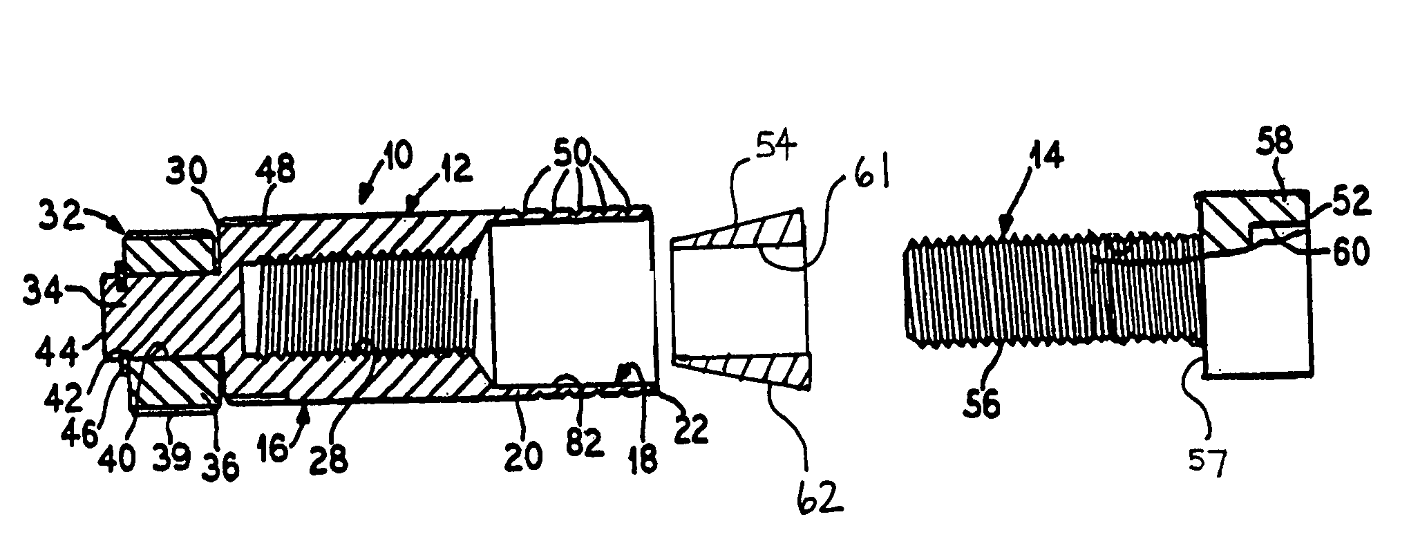
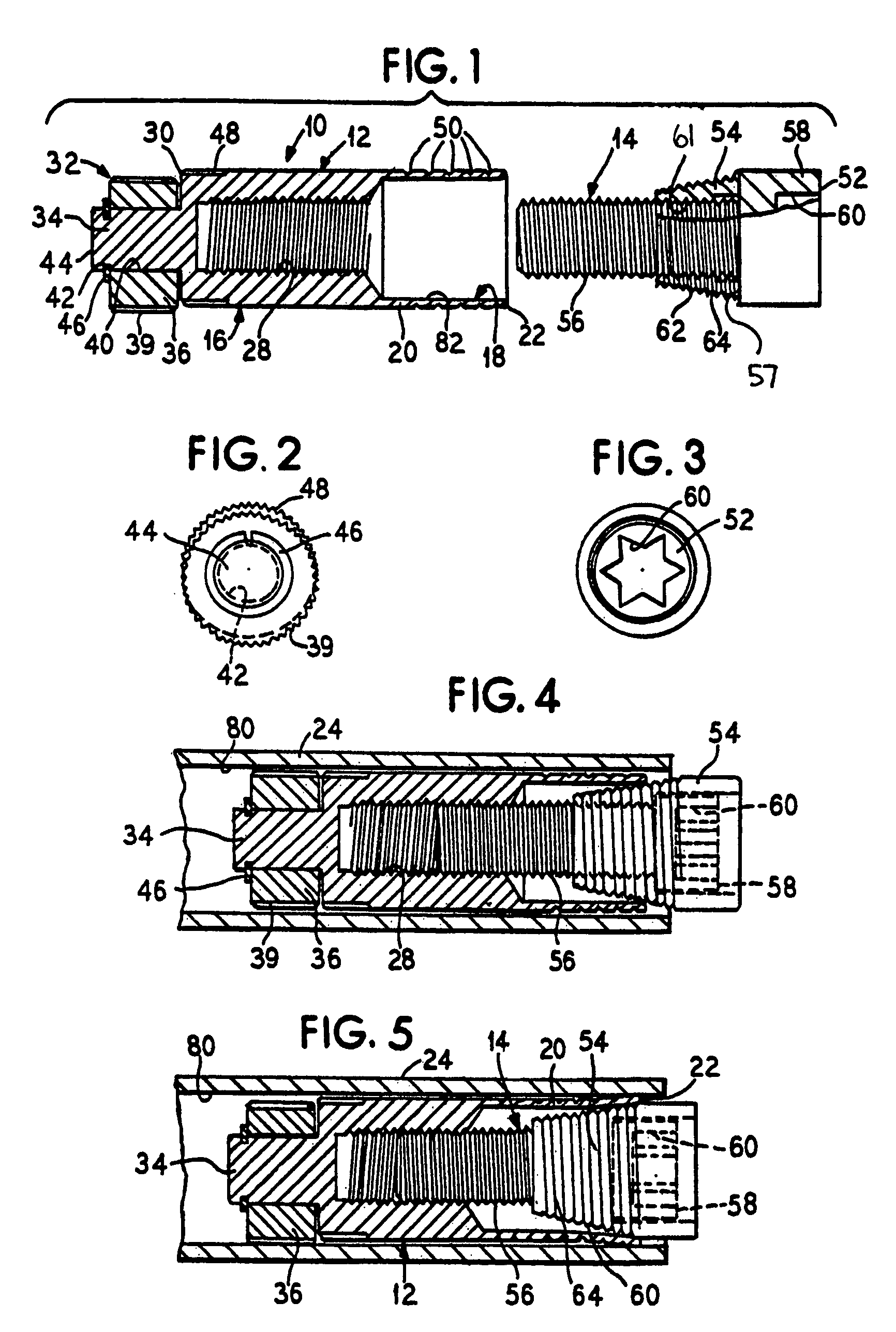
[0022]The present invention relates to a tube plug kit. The tube plug kit includes a tube plug having a housing member and a locking member. The housing member has a longitudinal bore that has a smooth portion in communication with a threaded portion. The locking member is mounted on the housing member for locking the inserted housing member against rotation relative to a tube. The tube plug kit also includes an insert member having a threaded end portion received within the threaded portion of the bore and an enlarged portion positioned to be drawn within the smooth portion of the longitudinal bore in response to rotation of the insert member in the longitudinal bore. The kit also includes an actuating tool and a tapered member between the enlarged portion of the insert member and the longitudinal bore of the housing member. The enlarged portion has a recess therein for receiving the actuating tool. Since the tube plug kit uses an actuating tool, the kit does not require the use o...


PUM


Abstract

A tube plug kit for sealing the end of a tube is provided. The tube plug kit includes a tube plug having a housing member and a locking member, an insert member having a threaded end portion received within the threaded portion of the bore and an enlarged portion positioned to be drawn within the smooth portion of the longitudinal bore in response to rotation of the insert member in the longitudinal bore. The tube plug kit also includes an actuating tool and a tapered member between the enlarged portion of the insert member and the longitudinal bore of the housing member. The enlarged portion has a recess therein for receiving the actuating tool.

Description

BACKGROUND OF THE INVENTION[0001]The present invention relates to improvements for a plug used to form a seal for tubes, pipes and similar conduits which transport steam, liquid or gases under pressure.[0002]An earlier version of this type of plug commercially exploited by the present Applicant is disclosed in previous U.S. Pat. Nos. 4,653,540 and 5,289,851, the specifications of which are hereby incorporated by reference. The plug disclosed in U.S. Pat. No. 4,653,540 comprises a hollow housing member which has at one end a relatively large open bore surrounded by a thin wall, and a relatively smaller threaded bore which communicates with the larger bore. An insert member is provided which, in use, is threaded into the smaller bore thereby causing a tapered member, which may be formed on the insert member, to engage the open end of the large bore causing it to expand and bear against the wall of a heat exchanger tube into which the heat exchanger tube plug has been inserted. During ...

Claims


Application Information

Patent Timeline
IPC IPC(8): F16L55/13F16L55/10F28F11/02
CPCF28F11/02F16L55/13
Inventor JORGENSEN, GLENN F.
Owner JNT TECHN SERVICES
Why Eureka
Try Eureka