Turbine engine shroud assembly including axially floating shroud segment

a technology for turbine engines and shroud segments, which is applied in the direction of machines/engines, liquid fuel engines, lighting and heating apparatus, etc., can solve the problems of not being able to tolerate the above described and currently used compressive force or similar restraint force against chording, and applying significant pressure to shrouds or shroud segments

Inactive Publication Date: 2005-04-26
GENERAL ELECTRIC CO
View PDF30 Cites 102 Cited by
  • Summary
  • Abstract
  • Description
  • Claims
  • Application Information

AI Technical Summary

Benefits of technology

[0007]Forms of the present invention provide a turbine engine shroud assembly comprising at least one shroud segment floating axially independently of other engine members disposed in adjacent juxtaposition with the shroud segment. In one embodiment, the shroud assembly includes at least one shroud segment, and generally a plurality of segments, including therein a shroud segment support wall surface extending generally axially into and at least partially through the segment. In that embodiment, the shroud assembly includes a shroud hanger disposed in axial juxtaposition with the shroud segment and having at least one support projection secured with the shroud hanger. The projection, that can be in the form of a pin, extends generally axially from the shroud hanger into the shroud segment at the shroud segment support wall surface, supporting the shroud segment releasably at the shroud segment support wall surface within the shroud segment. Accordingly, the shrou

Problems solved by technology

Such axial movement, that occurs as a result of adjacent members applying pressure on an adjacent member such as a shroud during engine operation, can result in application of significant pressure to a shroud or shroud segment.
Shroud segments made from CMC type materials, although having certain higher temperature capabilities than those of a metallic t

Method used


Image

  • Turbine engine shroud assembly including axially floating shroud segment
  • Turbine engine shroud assembly including axially floating shroud segment
  • Turbine engine shroud assembly including axially floating shroud segment

Examples


Embodiment Construction

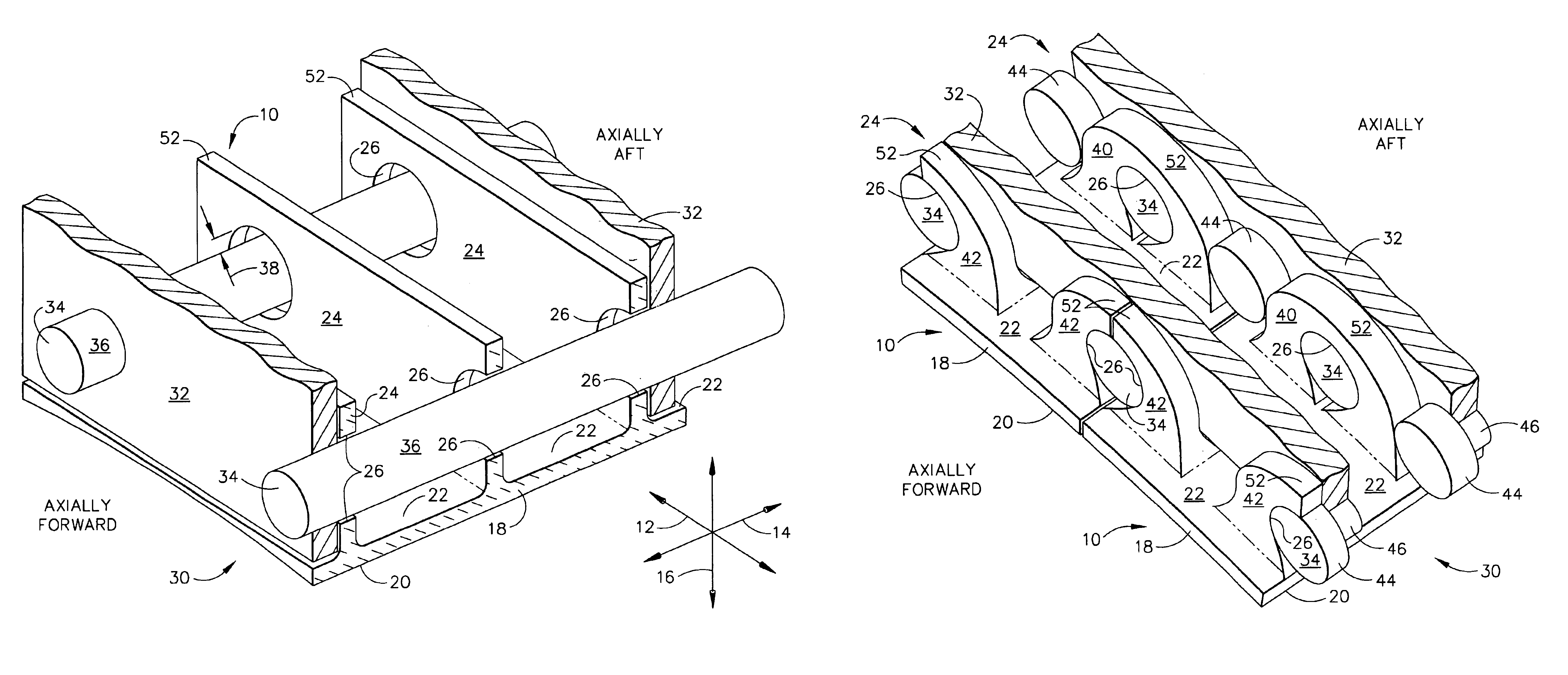
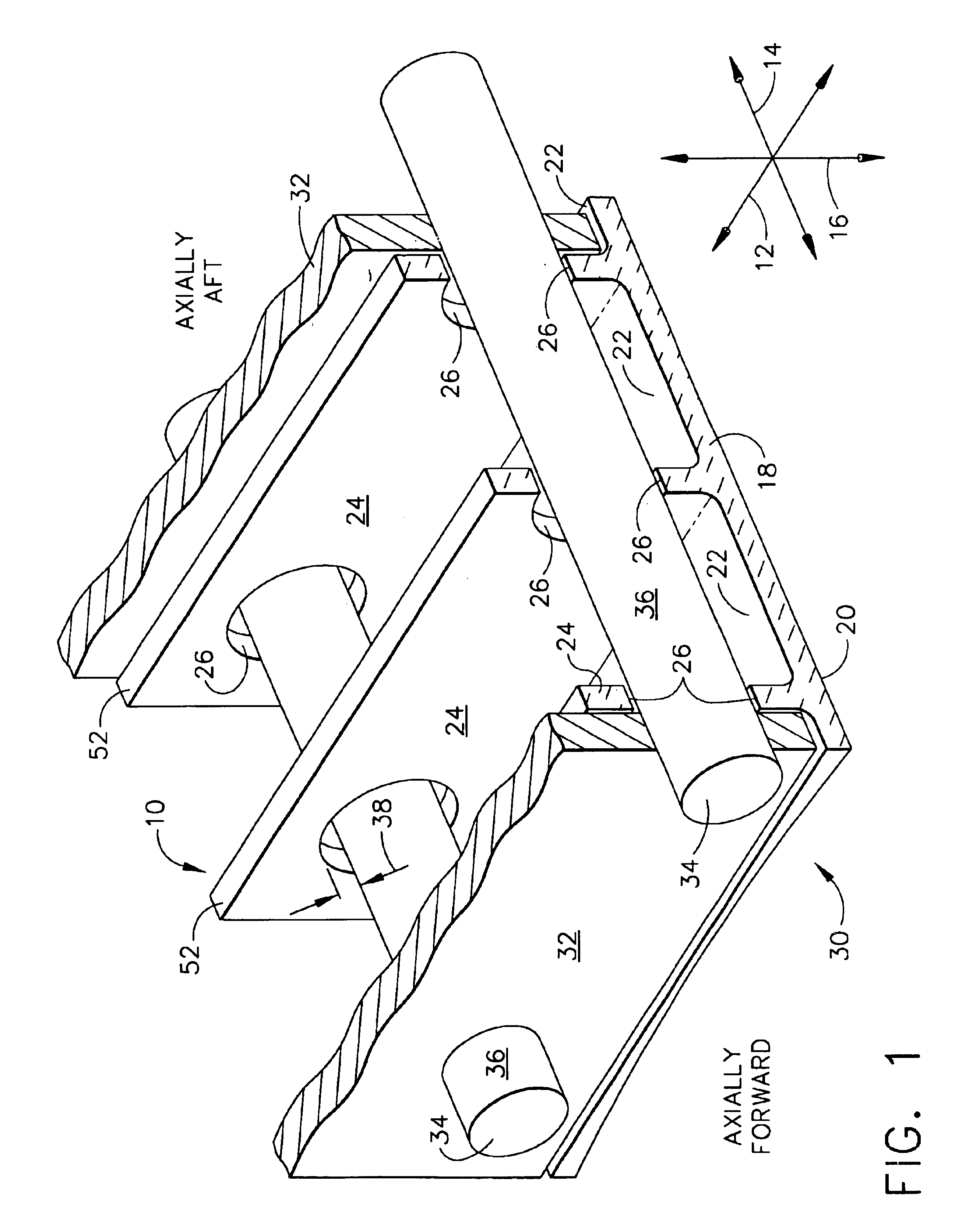
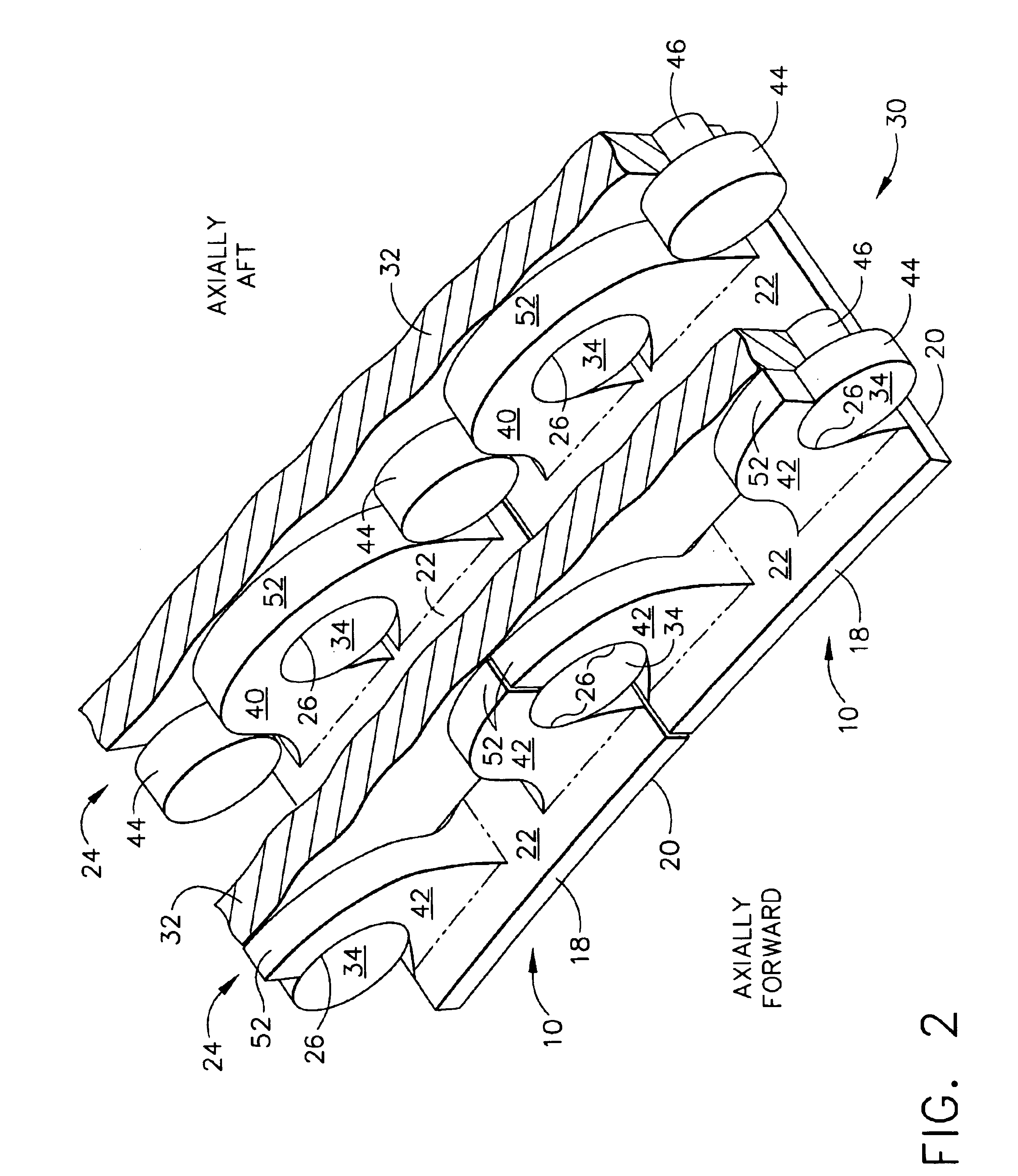
[0015]The present invention will be described in connection with an axial flow gas turbine engine for example of the general type shown and described in the above identified Proctor et al patent. Such an engine comprises a plurality of cooperating engine members and their sections in serial flow communication generally from forward to aft, including one or more compressors, a combustion section, and one or more turbine sections disposed axisymmetrically about a longitudinal engine axis. Accordingly, as used herein, phrases using the term “axially”, for example “axially forward” and “axially aft”, are directions of relative positions in respect to the engine axis; phrases using forms of the term “circumferential” refer to circumferential disposition generally about the engine axis; and phrases using forms of the term “radial”, for example “radially inner” and “radially outer”, refer to relative radial disposition generally from the engine axis.

[0016]It has been determined to be desir...


PUM


Abstract

At least one shroud segment, floating axially independently of adjacent turbine engine shroud assembly members, includes a segment body comprising a radially outer surface and a radially outwardly projecting segment support that includes an axial support wall surface therein. The assembly includes a shroud hanger in axial juxtaposition with the segment support, and at least one axial support projection from the shroud hanger into the segment support at the support wall surface. The support projection supports the shroud segment releasably at the support wall surface sufficiently to enable relative axial movement of the shroud segment on the support projection independently of the shroud hanger and adjacent engine members.

Description

[0001]The Government has rights in this invention pursuant to Contract No. F33615-97-C-2778 awarded by the Department of Air Force.BACKGROUND OF THE INVENTION[0002]This invention relates generally to turbine engine articles disposed about rotating articles, for example a turbine shroud, including a surface exposed to elevated temperature engine gas flow, and to their assemblies about rotating blades. More particularly, it relates to air cooled gas turbine engine shroud segments and to shroud assemblies, for example used in the turbine section of a gas turbine engine, especially segments made of a low ductility material.[0003]Typically, a plurality of gas turbine engine stationary shroud segments assembled circumferentially about an axial flow engine axis and radially outwardly about rotating blading members, for example about turbine blades, defines a part of the radial outer flowpath boundary over the blades. As has been described in various forms in the gas turbine engine art, it ...

Claims


Application Information

Patent Timeline
IPC IPC(8): F01D11/08F02C7/20
CPCF01D11/08F02C7/20F05D2300/603F05D2240/11F05D2230/642F05D2250/41
Inventor GLYNN, CHRISTOPHER CHARLESALFORD, MARY ELLENNOE, MARK EUGENEDARKINS, JR., TOBY GEORGE
Owner GENERAL ELECTRIC CO
Why Eureka
Try Eureka