Gas generator

a generator and gas technology, applied in the direction of diaphragm valves, hot gas positive displacement engine plants, mechanical equipment, etc., can solve the problem of uncontrollable influence on the cross-section of the generator

Inactive Publication Date: 2005-05-03
TRW AIRBAG SYST
View PDF8 Cites 15 Cited by
  • Summary
  • Abstract
  • Description
  • Claims
  • Application Information

AI Technical Summary

Benefits of technology

[0003]It is an object of the invention to create a gas generator in which an influencing of the outflow behaviour of the generated gas is achieved in a simple manner.

Problems solved by technology

Thus, no sections or parts of the peripheral wall are retained in the region of the outflow opening which has just been freed, which could influence its cross-section in an uncontrolled manner.

Method used


Image

  • Gas generator
  • Gas generator
  • Gas generator

Examples


Embodiment Construction

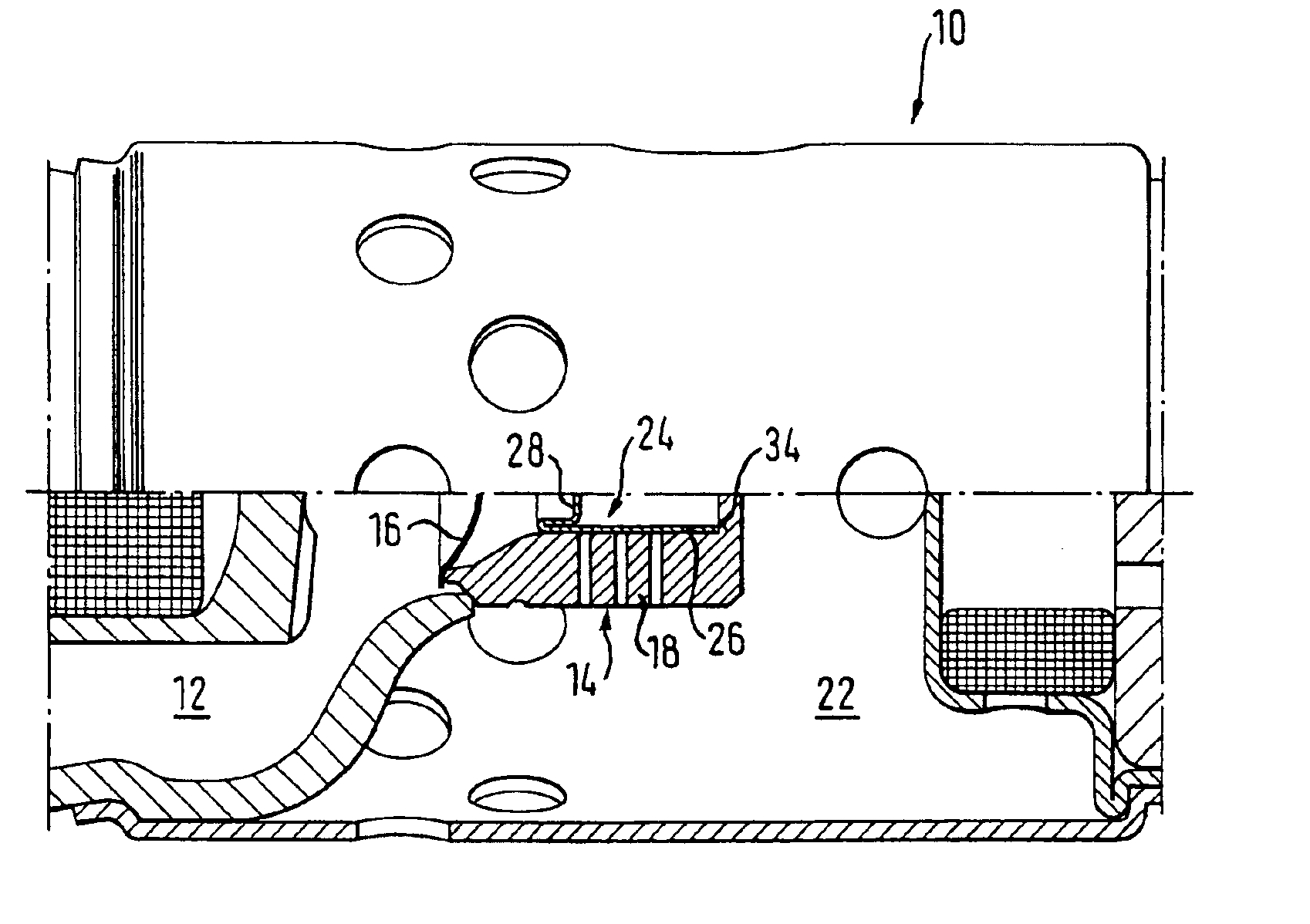
[0021]The gas generator 10 presented in the described example embodiment is a basically known hybrid gas generator, in which the generated gas originates mainly from a reservoir filled with compressed gas, constructed as a pressure container 12. In addition, a pyrotechnic charge (not illustrated) is provided for heating and possibly for igniting the gas.

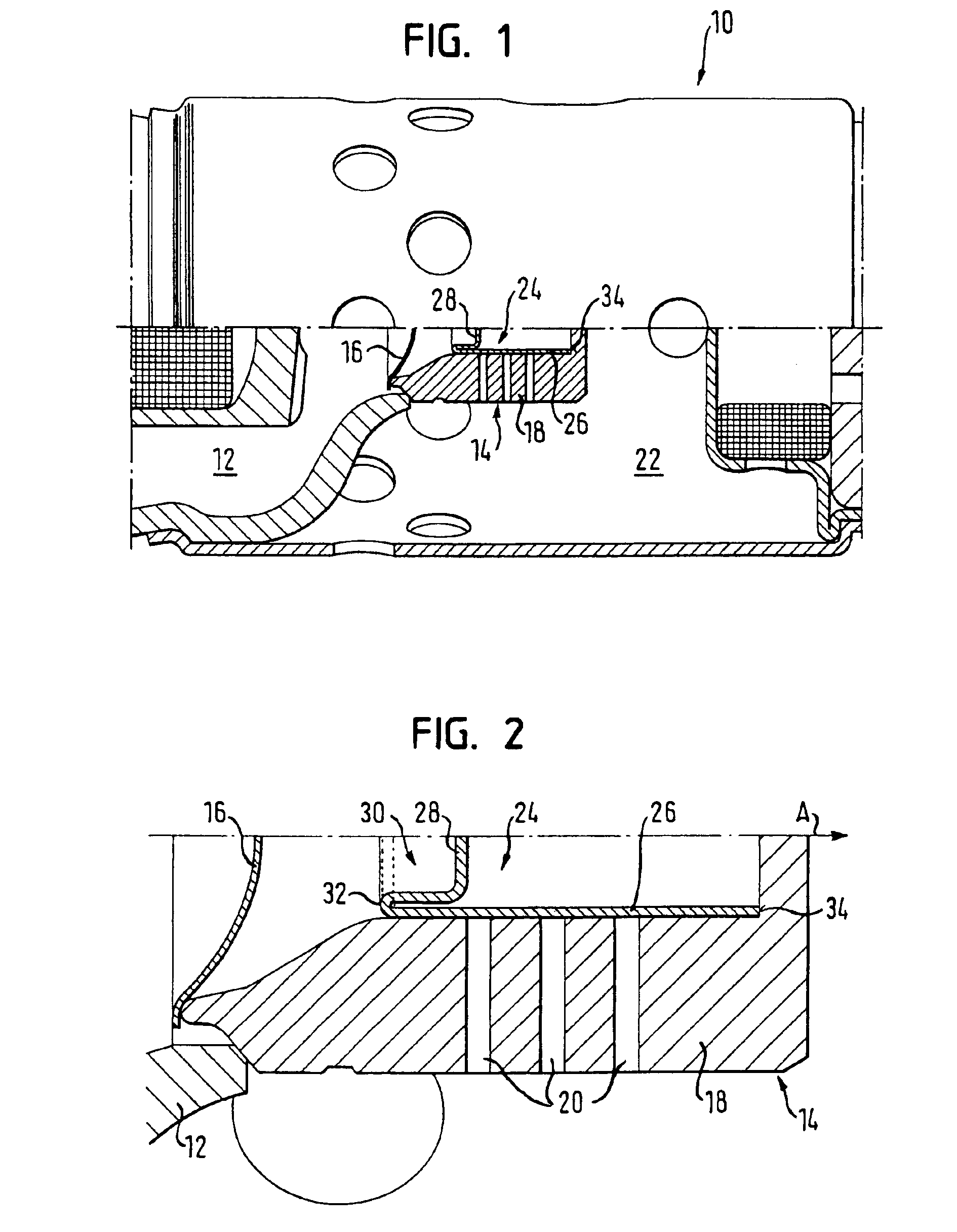
[0022]Adjoining one end of the pressure container 12 is an outflow chamber 14, which is closed with respect to the pressure container 12 by a membrane 16, which is only destroyed on an activation of the gas generator 10, so that the compressed gas can get from the pressure container 12 into the outflow chamber 14.

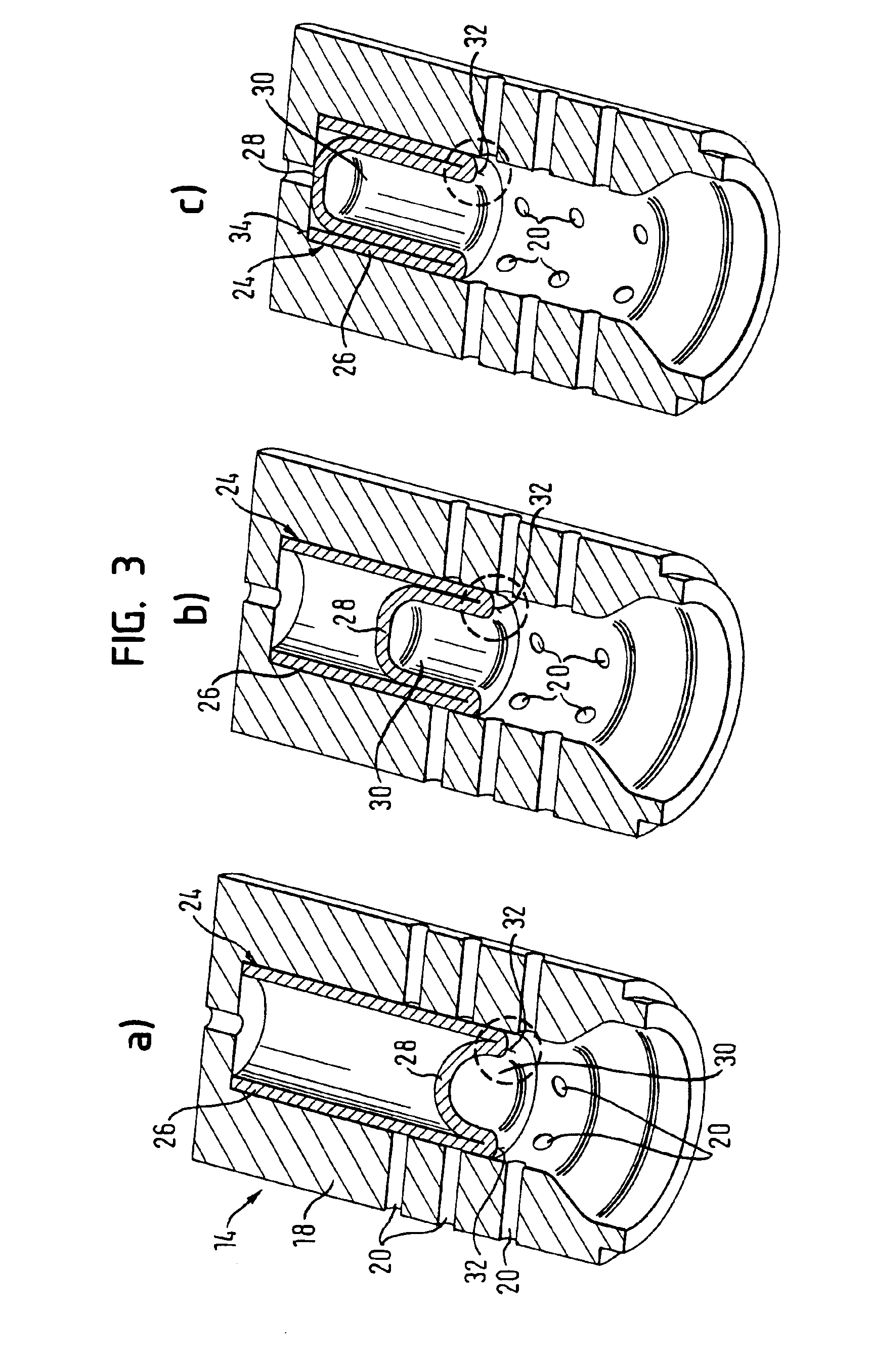
[0023]In a side wall 18 of the outflow chamber 14, several outflow openings 20 are arranged, through which the gas can flow via a diffusor chamber 22 to its final destination, e.g. a gas bag. As can be seen in FIGS. 3a to 3c, the outflow openings 20 are arranged in several groups located at different heights in relation to t...


PUM


Abstract

A gas generator comprises an outflow chamber and a freeing element. The outflow chamber contains at least briefly gas under pressure, when the gas generator is activated and at least one outflow opening is arranged in a side wall of the outflow chamber. The freeing element is arranged non-displaceably in the outflow chamber and has a peripheral wall and a base wall. The peripheral wall extends along the side wall and closes at least one outflow opening before an activation of the gas generator. The base wall is connected with the peripheral wall. The freeing element is constructed so that on exceeding a predetermined gas pressure in the outflow chamber, the base wall turns inwards under partial plastic deformation of the peripheral wall and at least one hitherto concealed outflow opening is freed by the plastic deformation of the peripheral wall.

Description

FIELD OF THE INVENTION[0001]The invention relates to a gas generator.BACKGROUND OF THE INVENTION[0002]The influencing of the chronological outflow behaviour of gas generated by a gas generator is of great importance for vehicle occupant restraint systems. For example, it is advantageous for the filling of a gas bag, if the quantity of gas is emitted at least uniformly, viewed over time, or if at the start a smaller and then an increasing gas mass through-flow is made possible. In order to optimize the outflow behaviour, means are therefore used which free or close outflow openings of the gas generator, through which the gas can finally arrive at its destination, during the gas generation phase in line with specific objectives. Such means must operate reliably at high pressures and high temperatures, but at the same time are to be as favourably priced as possible and able to be installed without a great installation expenditure.BRIEF SUMMARY OF THE INVENTION[0003]It is an object of t...

Claims


Application Information

Patent Timeline
Patent Type & Authority Patents(United States)
IPC IPC(8): B60R21/26F16K7/02F16K7/00B60R21/261B60R21/264B60R21/272
CPCB60R21/26B60R21/261B60R21/264F16K7/02B60R21/272B60R2021/26094B60R21/2644
Inventor FISCHER, JOACHIMGABLER, MICHAELHOFMANN, ACHIM
Owner TRW AIRBAG SYST
Why Eureka
Try Eureka