
Adjustable gripping tool

a technology of adjustable gripping and tool, which is applied in the direction of manufacturing tools, wrenches, tubes shearing machines, etc., can solve the problems of affecting the workpiece, and affecting the workpiece evenly

Active Publication Date: 2005-05-10
LOGGERHEAD TOOLS LLC
View PDF46 Cites 47 Cited by
  • Summary
  • Abstract
  • Description
  • Claims
  • Application Information

AI Technical Summary

Benefits of technology

"The present invention is an adjustable gripping tool that can be manually operated and self-energizes during use. The tool has the ability to automatically size and resize to engage different workpieces, de-energize upon release of actuation force, and provide offsetting forces for stability in operation. The tool can engage workpieces axially and radially, and provide symmetrically balanced and efficient gripping forces. The tool is designed to minimize distortion of the workpiece, decrease costs, increase productivity, and provide multi-access engagement of the workpiece. The technical effects of the invention include improved grip, reduced stress risers, and efficient workpiece manipulation."

Problems solved by technology

Each of the prior art devices have disadvantages.
The socket device is limited in its effective range of dimensional capability.
The plier-type devices fail to engage the workpiece evenly around or within the circumference with proper offsetting forces and stability which aides in operation of the tool.
The tube cutting devices cannot be used with one hand.
Another disadvantage of tube cutting devices, in particular, knife blade cutters, is that the tubing is often distorted as a result of the asymmetrical cutting forces applied by the blade against the tube.
Prior art crimping devices cannot create symmetrically balanced crimps with a simple hand tool.
Also the previously available tools for wrench applications could not be easily sized to the workpiece.

Method used


Image

  • Adjustable gripping tool
  • Adjustable gripping tool
  • Adjustable gripping tool

Examples


Embodiment Construction

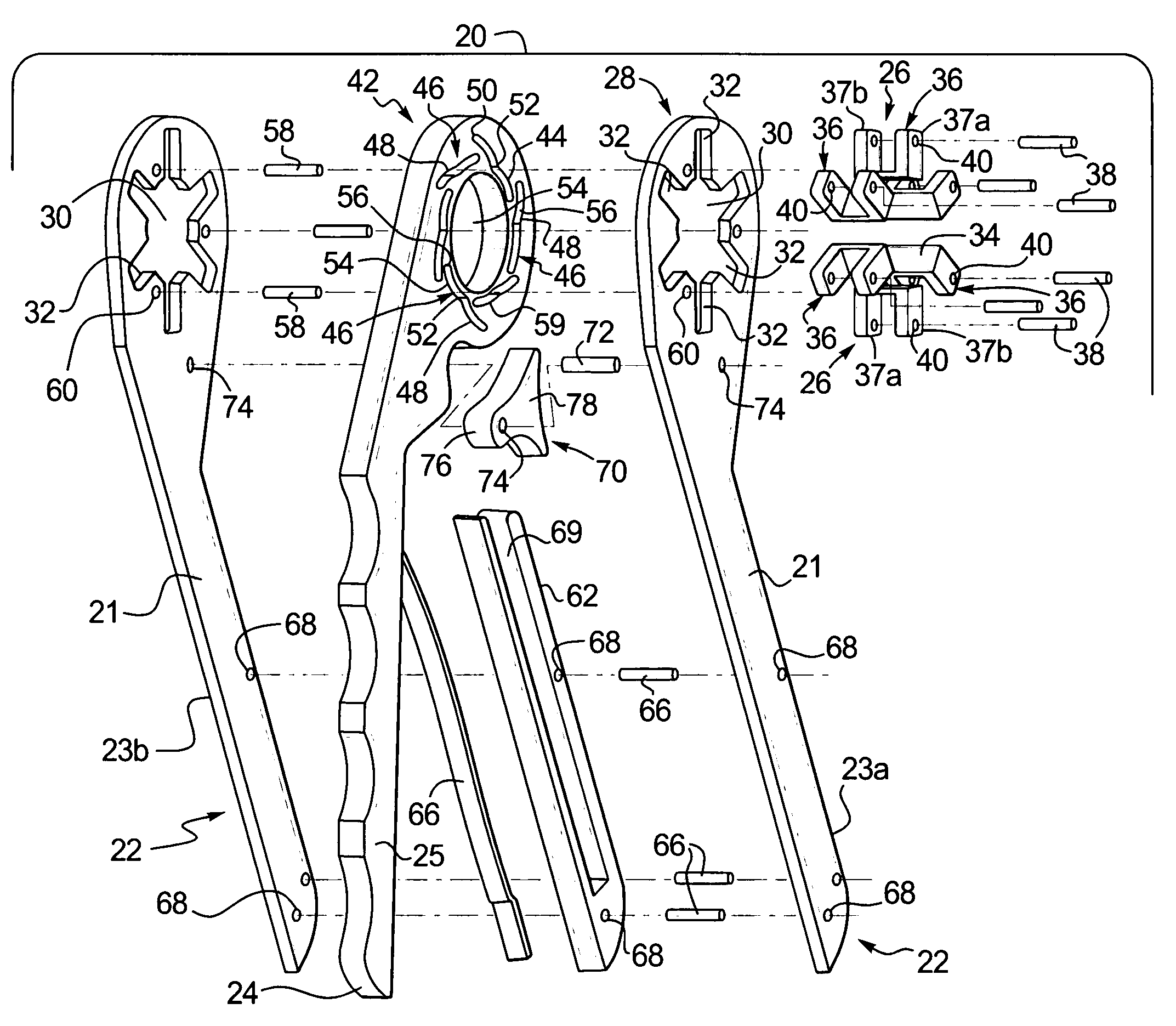
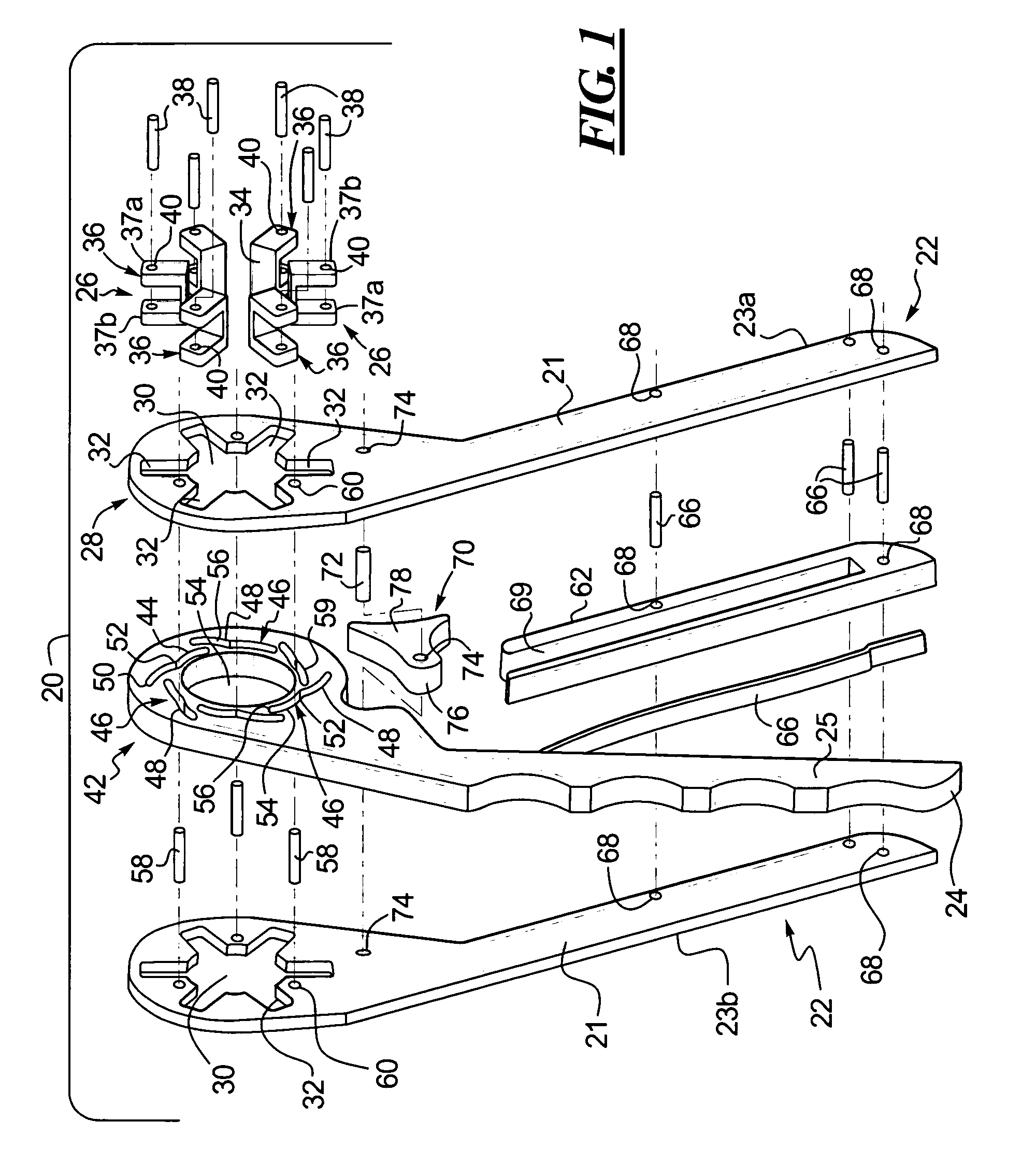
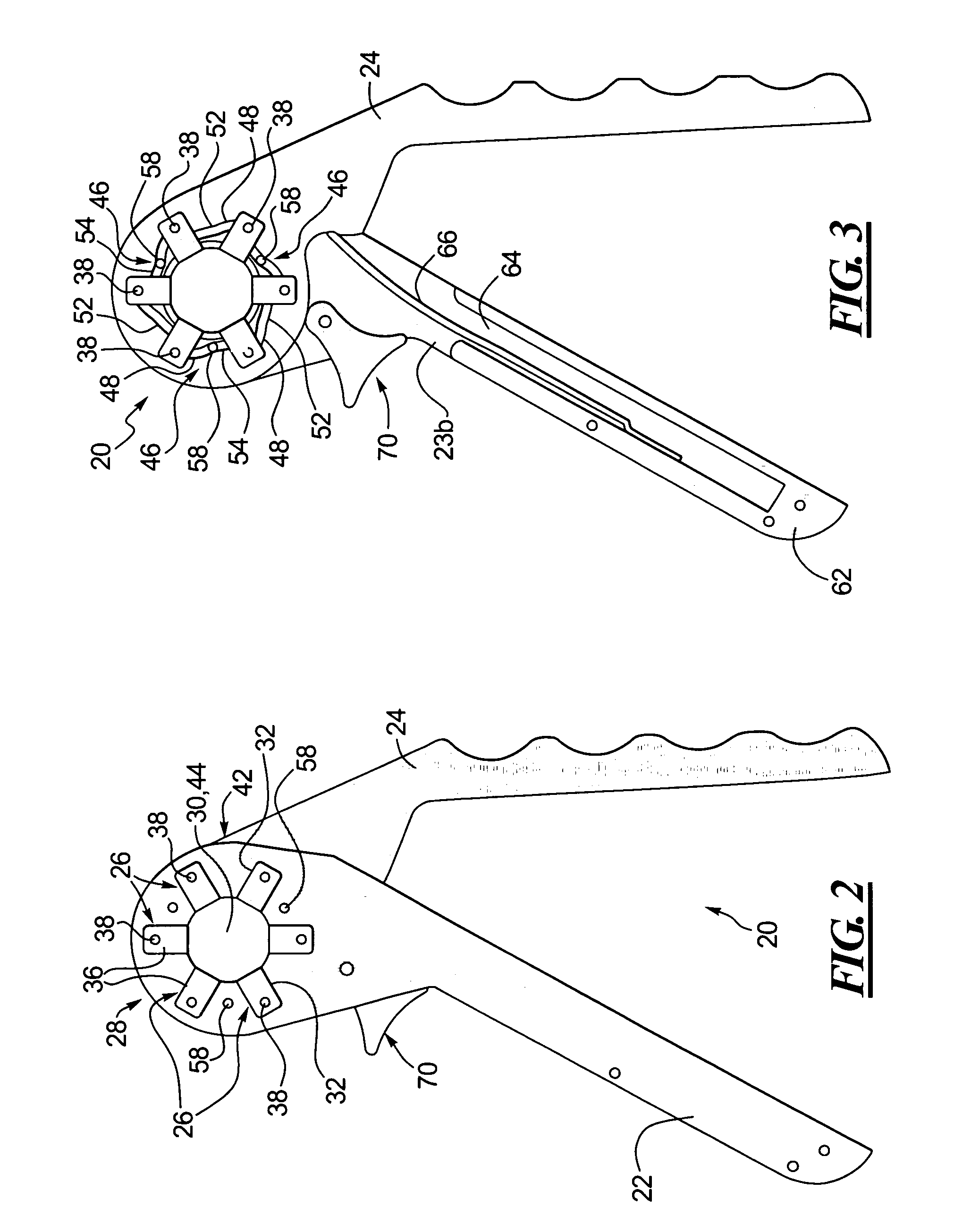
[0022]One principal aspect of the present invention is directed to an adjustable gripping tool for engaging a workpiece to impart work thereto. The gripping tool includes a first element and a second element connected for a relative angular movement which when activated generates movement of at least one gripping or workpiece engaging element. The first element includes a gripping portion configured to engage the workpiece including a first opening, at least one guide extending from the first opening and at least one gripping element. Each at least one gripping element includes a body portion adapted for engaging a workpiece, an arm portion configured to engage one of the guides and a force transfer element contiguous with the arm portion. The second element includes an actuation portion having a second opening concentric with the first opening and at least one slot disposed adjacent the second opening. Each of the slots has a first section configured to engage one of the force tran...


PUM

PropertyMeasurementUnit
forceaaaaaaaaaa
actuating forceaaaaaaaaaa
diameteraaaaaaaaaa

Abstract

A self-energizing and de-energizing adjustable gripping tool for engaging a workpiece to impart movement thereto includes a first element and second element connected for relative angular movement. The second element includes an actuation portion having a plurality of slots. Each of the slots includes a first section and a second section wherein the first and second sections each define divergent paths. The first element includes a gripping portion having a plurality of gripping elements and a plurality of aligning elements. Each gripping element has a pin connected thereto. One of the aligning elements is disposed between a pair of adjacent gripping elements. One of the force transfer elements engages one first section and one of the aligning elements engages one second section such that movement of the second element relative to the first element results in the first sections contacting each of the force transfer elements to actuate the gripping elements and the second sections contacting the aligning elements to maintain orientation of the first element with respect to the second element.

Description

BACKGROUND OF THE INVENTION[0001]This invention pertains to a hand tool and more particularly, to an adjustable gripping tool which, as a result of manual operation, self-energizes, automatically configures to engage differently dimensioned and shaped workpieces and de-energizes upon release of actuating force.[0002]Various types of adjustable gripping tools are known in the art. Specifically, several known adjustable gripping tools are embodied in the form of a “crescent” wrench, an adjustable socket wrench, pipe wrench, vice grips, crimpers, bolt and nut cutters, pipe and tube cutters, and various other “plier-type” gripping tools. A crescent wrench is an adjustable open end wrench that has stationary rotatable screw which engages a toothed rack formed on a first jaw element movable with respect to the second jaw element extending from the first element. The adjustable socket wrench includes a shell housing movable elements, such that movement of the first element with respect to ...

Claims


Application Information

Patent Timeline
Patent Type & Authority Patents(United States)
IPC IPC(8): B25B13/00B25B13/44B25B13/18B23D21/06B23D21/10B25B27/10B26D3/16
CPCB23D21/06B23D21/10B26D3/169B25B13/44B25B27/10B25B13/18B25B13/00
Inventor BROWN, DANIEL P.
Owner LOGGERHEAD TOOLS LLC
Learn More