

Dry-ice blast device
a blast device and dry-ice technology, applied in the direction of abrasive blasting machines, grinding/polishing apparatus, manufacturing tools, etc., can solve the problems of annoying noise generated near the operator, continuous work unbearable, breakage or excessive wear of dry-ice particles, etc., to achieve the effect of eliminating or alleviating
- Summary
- Abstract
- Description
- Claims
- Application Information
AI Technical Summary
Benefits of technology
Problems solved by technology
Method used
Image

Examples
Embodiment Construction
[0032]Preferred embodiments of the present invention will be described below in detail with reference to the accompanying drawings.
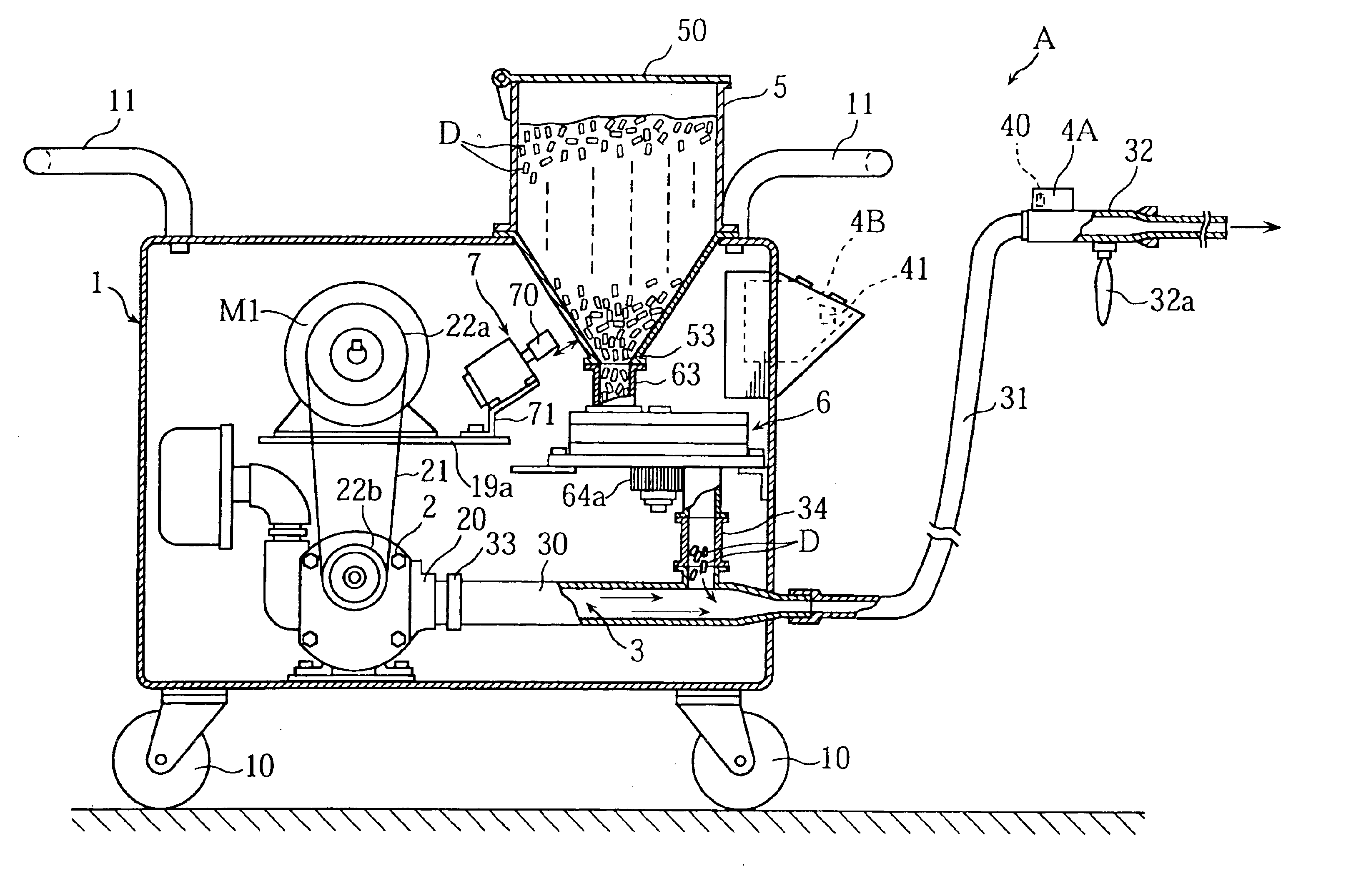
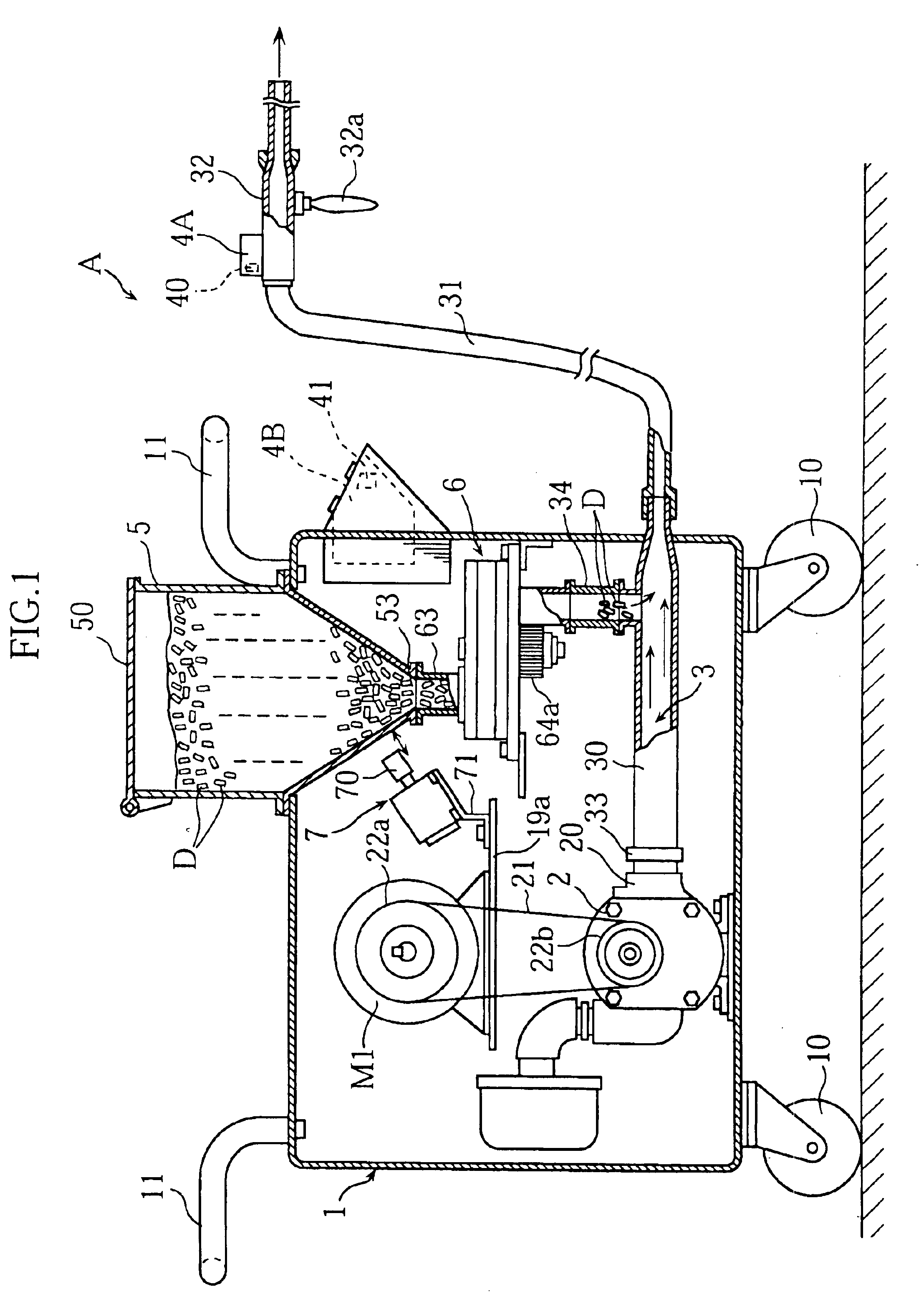
[0033]FIG. 1 illustrates an embodiment of a dry-ice blast device according to the present invention. The dry-ice blast device A according to this embodiment comprises a transferable frame 1, an air compressor 2, a pipe 30 connected to the discharge pipe 20 of the compressor 2, a hose 31, a nozzle 32, an operation unit 4A, a controller 4B, a hopper 5, a rotary feeder 6 and a knocker 7.
[0034]The transferable frame 1 is generally in the form of a box. Other parts constituting the dry-ice blast device A are directly or indirectly mounted to the transferable frame 1. The transferable frame 1 is provided with a plurality of wheels 10 for easy movement on the ground. At least one handle 11 is attached to the top of the frame 1.
[0035]The air compressor 2, which may be a Root's blower, can produce a large amount of air flow having a low pressure and high speed. T...
PUM
| Property | Measurement | Unit |
|---|---|---|
| pressure | aaaaa | aaaaa |
| pressure | aaaaa | aaaaa |
| length | aaaaa | aaaaa |
Abstract
Description
Claims
Application Information