Light-emitting unit, light-emitting unit assembly, and lighting apparatus produced using a plurality of light-emitting units

a technology of light-emitting units and lighting apparatuses, which is applied in the direction of lighting and heating apparatus, semiconductor devices for light sources, coupling device connections, etc., can solve the problems of low degree of design freedom and limited number of shapes of this type of lighting apparatus

Inactive Publication Date: 2005-05-10
PANASONIC CORP
View PDF12 Cites 64 Cited by
  • Summary
  • Abstract
  • Description
  • Claims
  • Application Information

AI Technical Summary

Problems solved by technology

However, the number of shapes realized by this type of lighting apparatus is still limited, with there being only a low degree of design freedom.

Method used


Image

  • Light-emitting unit, light-emitting unit assembly, and lighting apparatus produced using a plurality of light-emitting units
  • Light-emitting unit, light-emitting unit assembly, and lighting apparatus produced using a plurality of light-emitting units
  • Light-emitting unit, light-emitting unit assembly, and lighting apparatus produced using a plurality of light-emitting units

Examples


first embodiment

(First Embodiment)

[0125]The following describes the first embodiment of the present invention by referring to drawings.

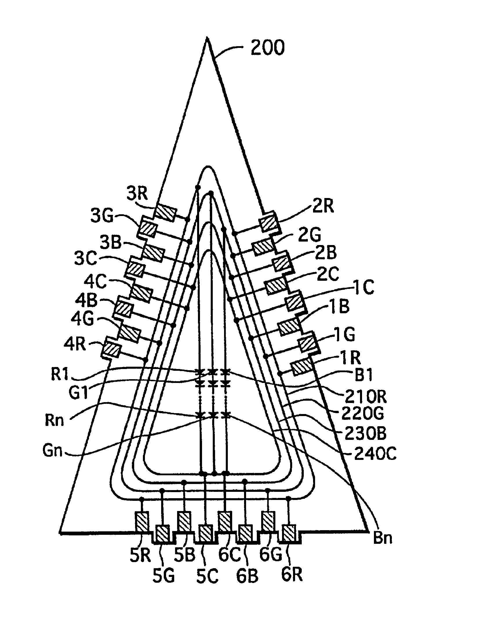
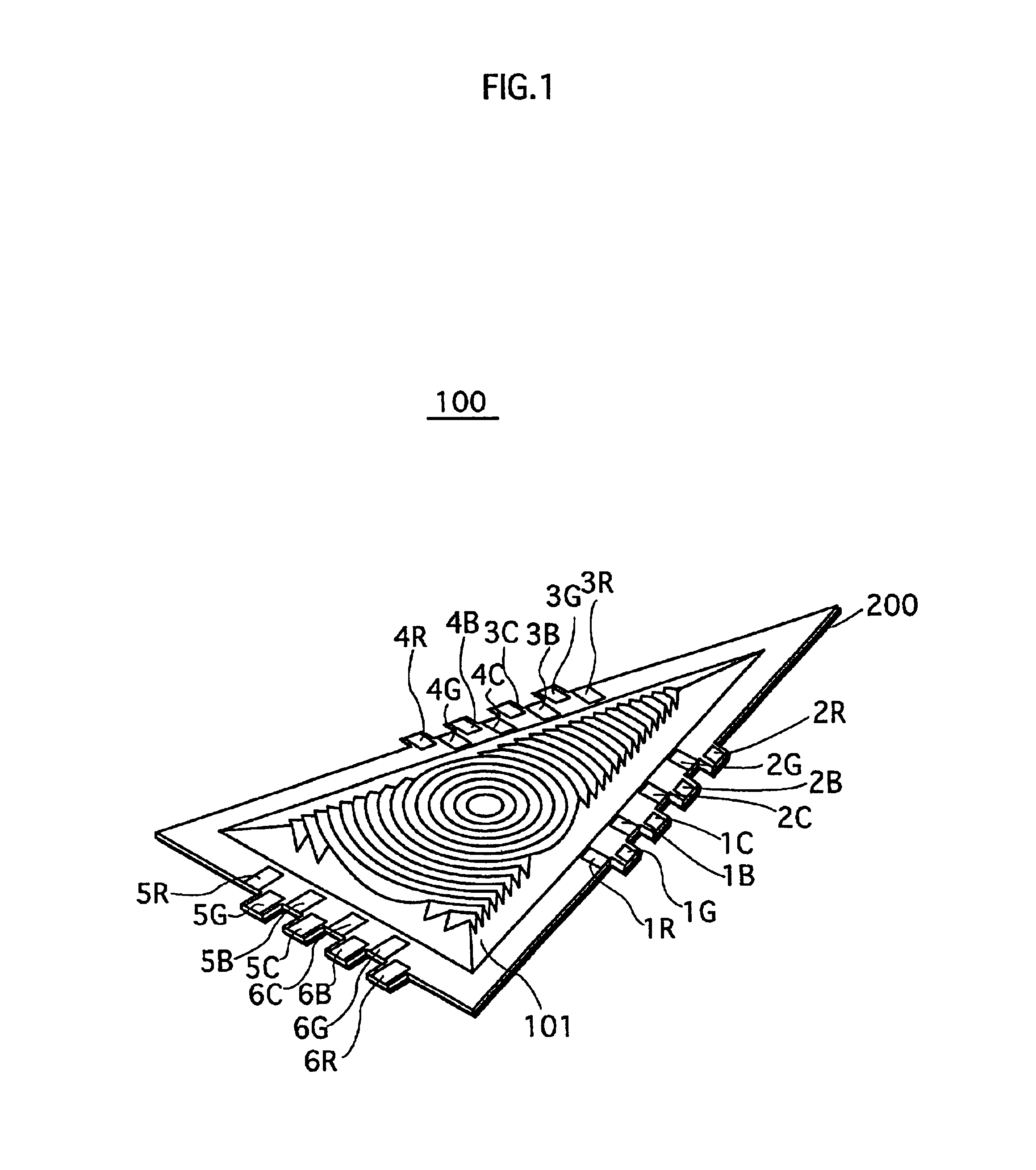
[0126]FIG. 1 is a perspective view showing an appearance of a light-emitting unit to which the first embodiment of the invention relates. A light-emitting unit 100 is shaped like an isosceles triangular plate (sheet). The light-emitting unit 100 emits light from a main surface, using power which is supplied through any of the feeder terminals (1R-6R, 1G-6G, 1B-6B, and 1C-6C) provided on the sides of the isosceles triangle.

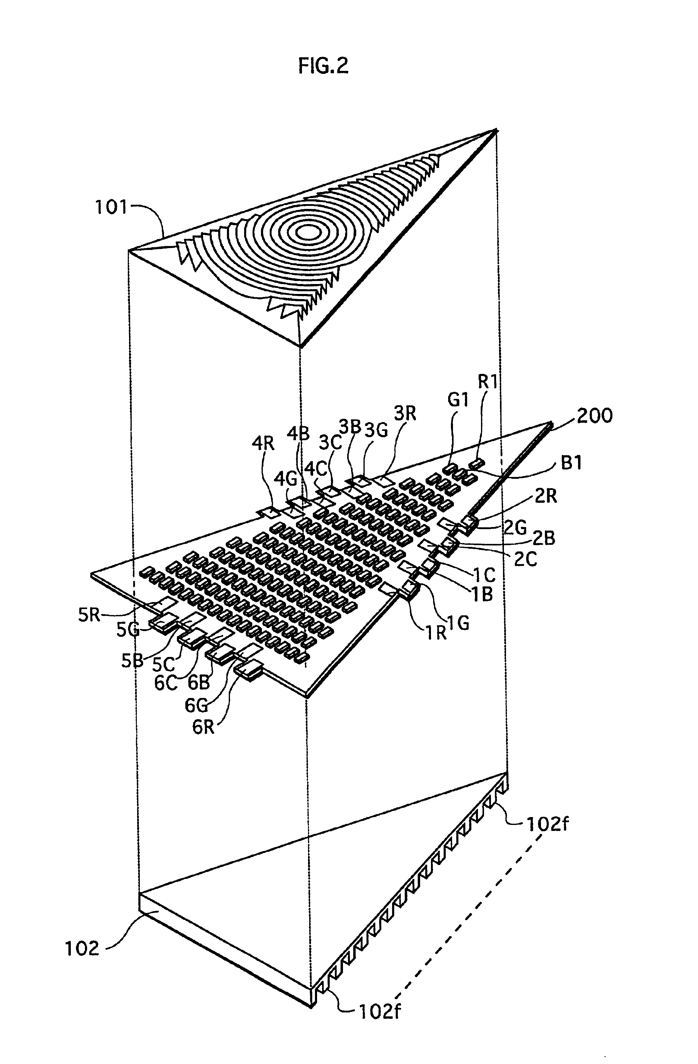
[0127]FIG. 2 is an exploded perspective view of the light-emitting unit 100.

[0128]As illustrated, the light-emitting unit 100 is roughly made up of a Fresnel lens 101, a multilayer flexible substrate (hereafter simply referred to as “multilayer substrate”) 200, and a radiating plate 102 which are placed one on top of the other. The Fresnel lens 101 is formed from an epoxy resin which is a translucent material. The multilayer substrate 200 has a num...

second embodiment

[0224]The second embodiment is fundamentally the same as the first embodiment, except that the shape of the light-emitting unit and the construction of the multilayer substrate are different. Accordingly, the parts which are the same as those in the first embodiment are either only briefly explained or their explanation is omitted, so that the following explanation focuses on the differences with the first embodiment.

[0225]In the second embodiment, reference numerals used in the drawings are expressed in five digits. The upper two digits of each reference numeral are equal to the number of the drawing in which the construction element designated by the reference numeral first appears.

[0226]Also, if the construction element designated by the reference numeral corresponds to a construction element shown in the first embodiment, the lower three digits of that reference numeral are equal to a reference numeral that is used in the first embodiment to designate the corresponding construct...

third embodiment

[0267]The third embodiment is similar to the second embodiment in that the light-emitting unit is hexagonal, but differs with the second embodiment in that feeder terminals are provided only on three alternate sides. Also, while the first and second embodiments mainly describe the case where LEDs of the three colors are used, the third embodiment describes the case where LEDs of a single color are used.

[0268]Though the third embodiment has a number of similarities to the first and second embodiments, its construction is described in detail without omitting those similarities.

(1. Overall Construction)

[0269]FIG. 35 is a perspective view showing an appearance of a lighting apparatus to which the third embodiment of the invention relates. In the drawing, a lighting apparatus 1 has seven light-emitting units 2a-2g and a base unit 30000. The light-emitting unit 2a-2g and the base unit 30000 are substantially regular hexagonal flat (sheet) units. The base unit 30000 has an E26 base (a scre...


PUM

PropertyMeasurementUnit
particle diameteraaaaaaaaaa
total thicknessaaaaaaaaaa

Abstract

A number of red LEDs, green LEDs, and blue LEDs are mounted on one surface of a polygonal flexible multilayer substrate. The LEDs are connected in series according to color. A red feeder terminal, a green feeder terminal, a blue feeder terminal, and a common terminal are provided on each of at least three sides of the periphery of the flexible multilayer substrate. Circuit patterns for connecting LEDs at the high-potential end of the red, green, and blue series-connected LEDs respectively to the red feeder terminals, green feeder terminals, and blue feeder terminals are provided to the flexible multilayer substrate. Also, a circuit pattern for connecting LEDs at the low-potential end of the red, green, and blue series-connected LEDs all to the common terminals is provided to the flexible multilayer substrate.

Description

[0001]This application is based on applications Nos. 2001-016663, 2001-287665, 2001-287666, and 2001-287668 filed in Japan, the contents of which are hereby incorporated by reference.BACKGROUND OF THE INVENTION[0002]1. Field of the Invention[0003]The present invention relates to a light-emitting unit, a light-emitting unit assembly, and a lighting apparatus manufactured using a plurality of light-emitting units.[0004]2. Related Art[0005]With diversification of fashions and consumer tastes, designs of various products, both movables and immovables, are increasingly diversified in recent years. Lighting apparatuses are no exception. Attractive and functional designs which are free from conventional shapes are being proposed.[0006]One example is a lighting apparatus that is assembled by connecting a plurality of flat light-emitting units. Such a lighting apparatus comes in several different shapes depending on how the plurality of light-emitting units are combined.[0007]However, the nu...

Claims


Application Information

Patent Timeline
Patent Type & Authority Patents(United States)
IPC IPC(8): H01L25/075H01L33/00H05K1/14F21K99/00H01L33/58H01L33/62
CPCF21K9/90H01L25/0753H01R13/7175F21K9/17F21K9/135H01R12/7076F21Y2111/007H01L33/58H01L33/62H05K1/14H05K1/142H01L2224/48464H01L2224/73265F21Y2101/02F21V3/0436H01L2924/3025H01L2224/48091H01L2924/00014H01L2924/00F21K9/232F21K9/27F21Y2115/10F21Y2107/40F21Y2115/20F21V3/062
Inventor NAGAI, HIDEOMATSUI, NOBUYUKITAMURA, TETSUSHISHIMIZU, MASANORI
Owner PANASONIC CORP
Why Eureka
Try Eureka