Caster roll

a technology of caster rolls and cores, applied in the field of caster rolls, can solve the problems of slipping forming roll gaps between the roll core and the roll shell, and affecting the mold shape of cast aluminum sheet materials

Inactive Publication Date: 2005-05-17
ARCONIC INC
View PDF42 Cites 35 Cited by
  • Summary
  • Abstract
  • Description
  • Claims
  • Application Information

AI Technical Summary

Benefits of technology

[0021]The first metal overlay and the at least one additional metal overlay may each be formed to a thickness of less than about 6 inches and, preferably, between about 0.010 to 6 inches. The first metal overlay may be a thermally conductive metal, such as copper, bronze, steel, and the like. The at least one additional metal overlay may be a metal alloy, such as a nickel, cobalt, copper, or titanium based alloy. The at least one additional metal overlay may also be steel. The at least one additional metal overlay may be a single metal overlay formed on the first metal overlay and be comprised of any of the metals identified hereinabove.

Problems solved by technology

It is generally known that the major cause of damage to prior art caster rolls is slipping between the roll core and the roll shell.
The slipping typically occurs between the grooved or channeled surface of the roll core and the roll shell, which results in the formation of roll gaps between the roll core and roll shell.
This leads to the aforementioned out-of-roundness (i.e., eccentricity) problem, which may ultimately result in misshaping the cast aluminum sheet material.
Another problem associated with current caster rolls includes cracking in the roll shell due to thermal gradient and accompanying leakage of coolant onto the roll shell, which is a safety concern.
Additionally, the thermal gradient along the surface of the roll core and roll core / roll shell slippage often cause the caster roll to distort or bend, which also may result in misshaping the cast aluminum sheet material during production runs.

Method used


Image

  • Caster roll
  • Caster roll
  • Caster roll

Examples


Embodiment Construction

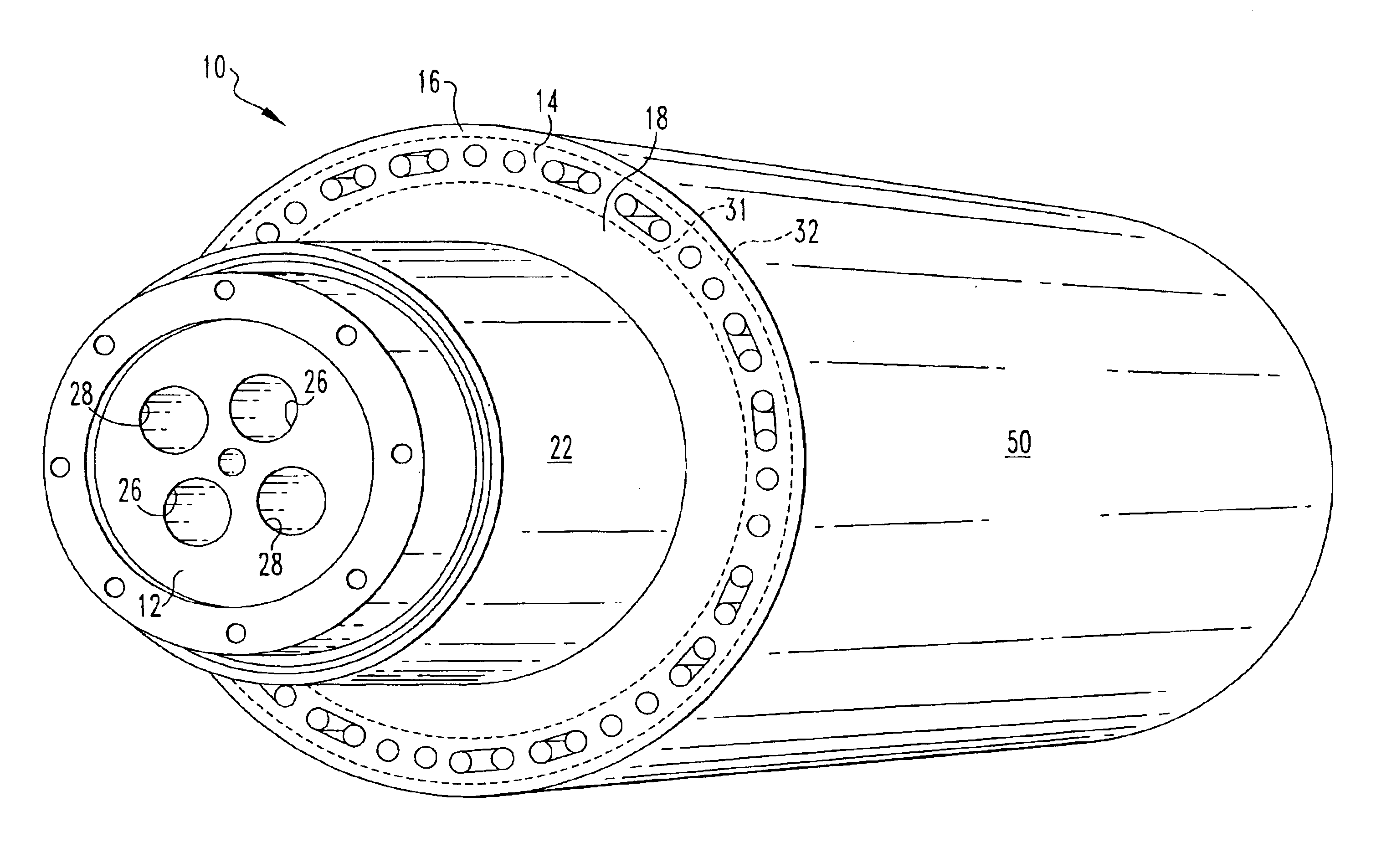
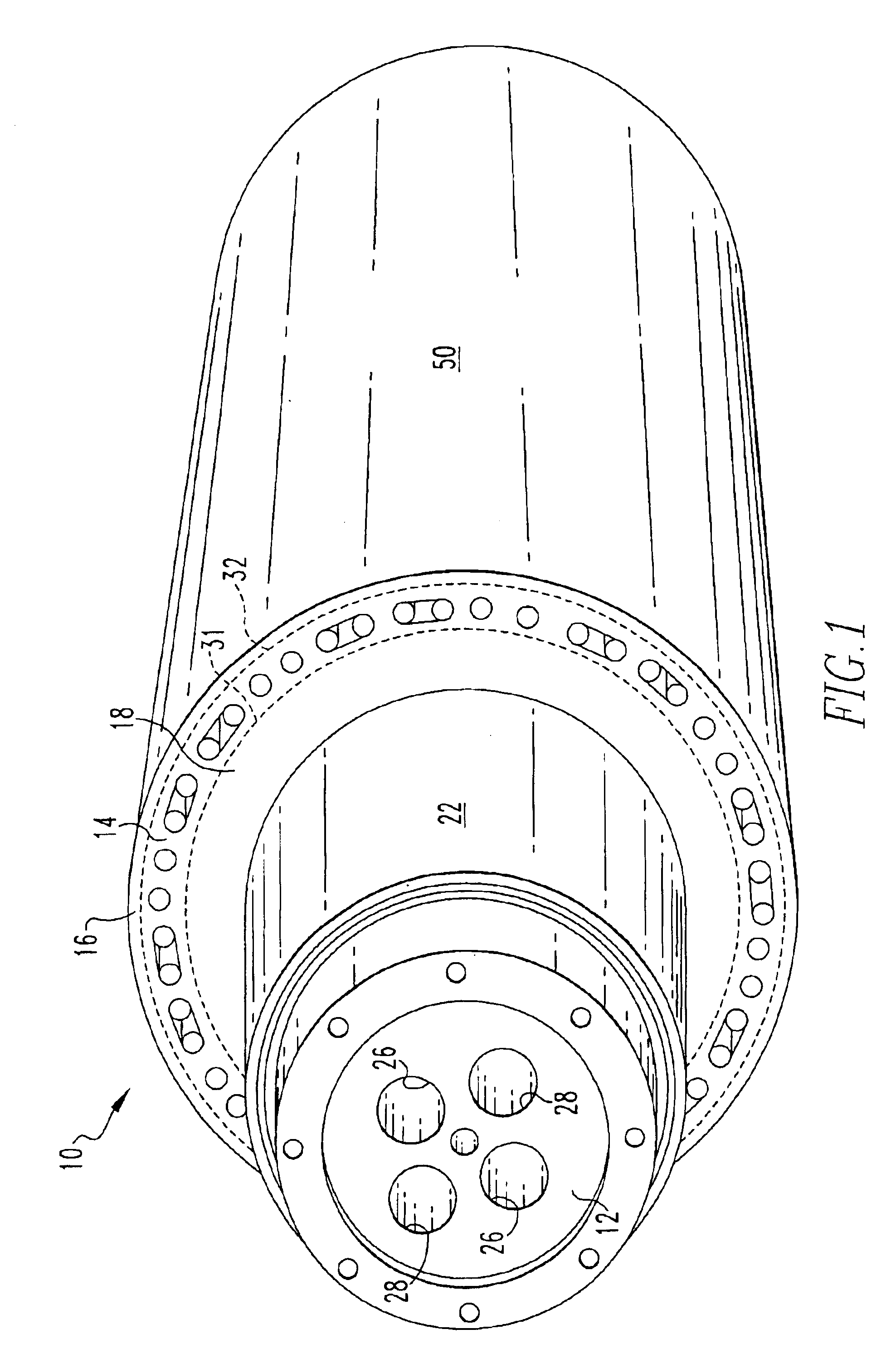
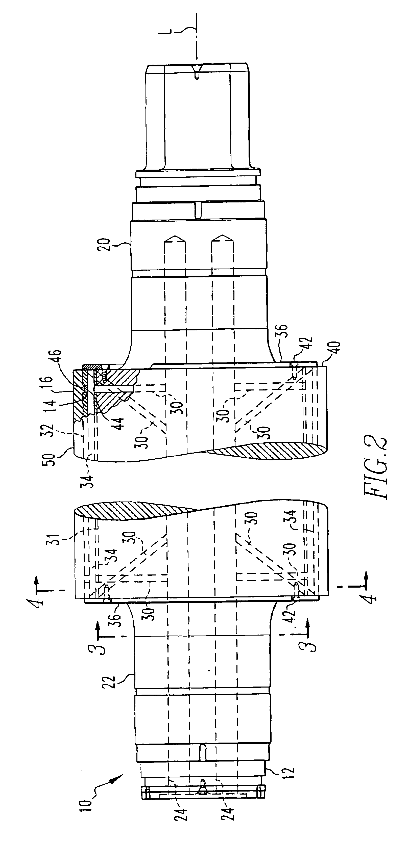
[0052]Referring to FIGS. 1-10, a caster roll 10 in accordance with the present invention is shown. The caster roll 10 is generally comprised of a roll core 12 and one or more metal overlays formed on the roll core 12. The roll core 12 is preferably solid as shown in the various accompanying figures, but may also be hollow (i.e., annular-shaped). In the embodiment of the caster roll 10 illustrated in FIGS. 1-10, two metal overlays are formed on the roll core 12. The two metal overlays are separately designated with reference numerals “14” and “16”, respectively, throughout this disclosure. Accordingly, the caster roll 10 will be described hereinafter in terms of two metal overlays, including a first metal overlay 14 formed directly on the roll core 12 and a second metal overlay 16 formed on top of the first metal overlay 14. However, other embodiments described in this disclosure comprise only one metal overlay on the roll core 12. Additionally, the present invention is intended to e...


PUM

PropertyMeasurementUnit
thicknessaaaaaaaaaa
thicknessaaaaaaaaaa
temperatureaaaaaaaaaa

Abstract

The caster roll (10) is used in the manufacture of metal plate, strip, sheet, or foil. The caster roll (10) includes a cylindrical roll core (12) and at least one metal overlay (14) formed on the roll core (12). The at least one metal overlay (14) defines a plurality of cooling passages (34) for conducting a cooling medium through the at least one metal overlay (14) to cool the roll (10) during use. Additional metal overlays (16) may be formed on top of the at least one metal overlay. (14). The cooling passages (34) may also be formed in the roll core (12).

Description

RELATED APPLICATION[0001]This application claims the benefit of U.S. Provisional Patent Application Ser. No. 60 / 438,721, filed Jan. 8, 2003, entitled “Caster Roll and Method of Manufacture”.BACKGROUND OF THE INVENTION[0002]1. Technical Field of the Invention[0003]The present invention relates to caster rolls used in the manufacturing of sheet material and methods of manufacturing caster rolls. More particularly, the present invention relates to an internally cooled caster roll having one or more layers of material, such as metal, formed on a roll core of the caster roll and methods of manufacturing the caster roll.[0004]2. Description of Related Art[0005]In the manufacture of cast aluminum plate, strip, sheet, or foil (hereinafter referred to as “aluminum sheet material”), conventional roll casting machines used to manufacture such aluminum sheet material typically have a twin-roll arrangement. In the twin-roll arrangement, a pair of substantially parallel, water-cooled, and counter...

Claims


Application Information

Patent Timeline
Patent Type & Authority Patents(United States)
IPC IPC(8): B22D11/06B21B27/06B21B27/03B21B27/08
CPCB22D11/0682B22D11/0651B21B27/03B21B2027/083B22D11/06
Inventor LIU, JOSHUA C.CREECH, TEDDY R.
Owner ARCONIC INC
Why Eureka
Try Eureka