Apparatus and method to indicate required compressor pressure for use with pneumatic tool device

a pneumatic tool and compressor technology, applied in the direction of manufacturing tools, nailing tools, stapling tools, etc., can solve the problems of increasing labor time and construction costs, limited life of pneumatic nail guns to drive nails, and inefficient tool functionality

Inactive Publication Date: 2005-05-17
BLACK & DECKER INC
View PDF9 Cites 32 Cited by
  • Summary
  • Abstract
  • Description
  • Claims
  • Application Information

AI Technical Summary

Benefits of technology

[0006]Accordingly, the present invention is directed to an apparatus and method of indicating the required compressor pressure for use with a pneumatic nail gun. In a first aspect of the present invention, a compressor pressure indication assembly for a pneumatic nail gun having a nail loading assembly comprises a nail verification assembly disposed on the nail loading assembly for identifying the length of a nail received in the nail loading assembly. A readout assembly is associated with the nail verification assembly and provides information to an operator of the pneumatic nail gun. Wherein, the compressor pressure indication assembly indicates the required compressor pressure when using the pneumatic nail gun.

Problems solved by technology

However, nail guns which employ air pressure (pneumatic nail guns) to drive nails have a limited life span due to the high pressures involved in their use.
This may result in inefficient tool functionality which may increase labor time and construction costs.
Further, this limited life span may result in lost time when the tool must be replaced.
Unfortunately, there is little in the way of help to a user of these pneumatic nail guns for avoiding shortening the life span of the nail gun due to improper compressor pressure use.
If the user is unaware of the difference in the nails then the compressor pressure will not be adjusted to maximize tool effectiveness.
This may result in increased wear on the tool which will shorten its useful life.
While it is known to provide a system of adjusting compressor pressure in correlation with nail size when the user is aware of the nail size, there is no protection against the unaware user or the user of a nail gun when the nails have been previously loaded into the nail gun and the user is unable to determine the nail size.
In these situations use of the nail gun may significantly decrease the useful life of the nail gun.

Method used


Image

  • Apparatus and method to indicate required compressor pressure for use with pneumatic tool device
  • Apparatus and method to indicate required compressor pressure for use with pneumatic tool device
  • Apparatus and method to indicate required compressor pressure for use with pneumatic tool device

Examples


Embodiment Construction

[0018]Reference will now be made in detail to the presently preferred embodiments of the invention, examples of which are illustrated in the accompanying drawings.

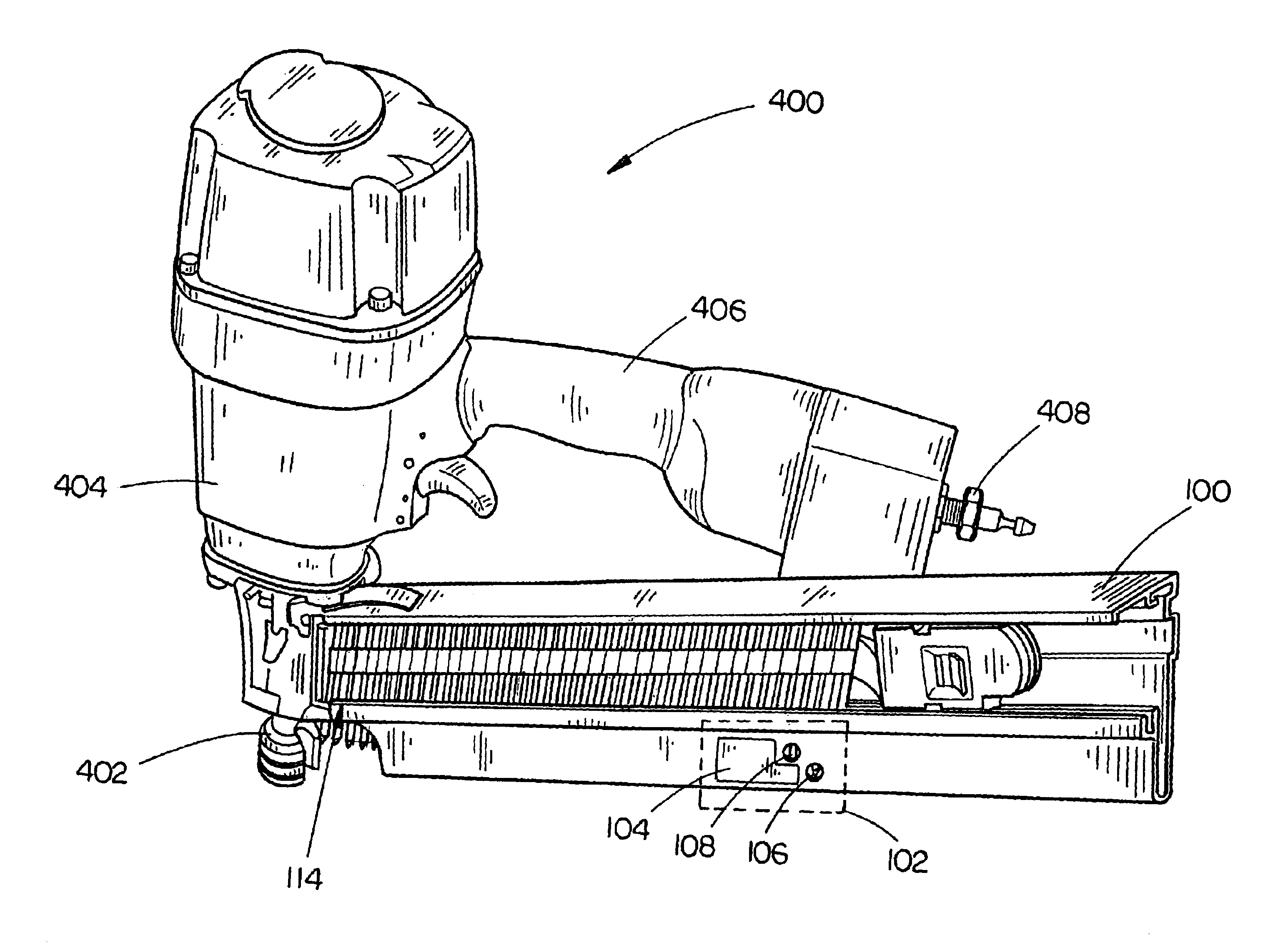
[0019]Referring generally now to FIGS. 1 through 5, exemplary embodiments of the present invention are shown. The present invention increases the effectiveness and useful life of a pneumatic nail gun through indication of proper compressor pressure correlated to the specific instrument being operated upon by the tool. An operator of the present invention is assured of an accurate indication of correct compressor pressure without requiring the user to remove already loaded instruments (e.g., nail magazine) from the pneumatic tool.

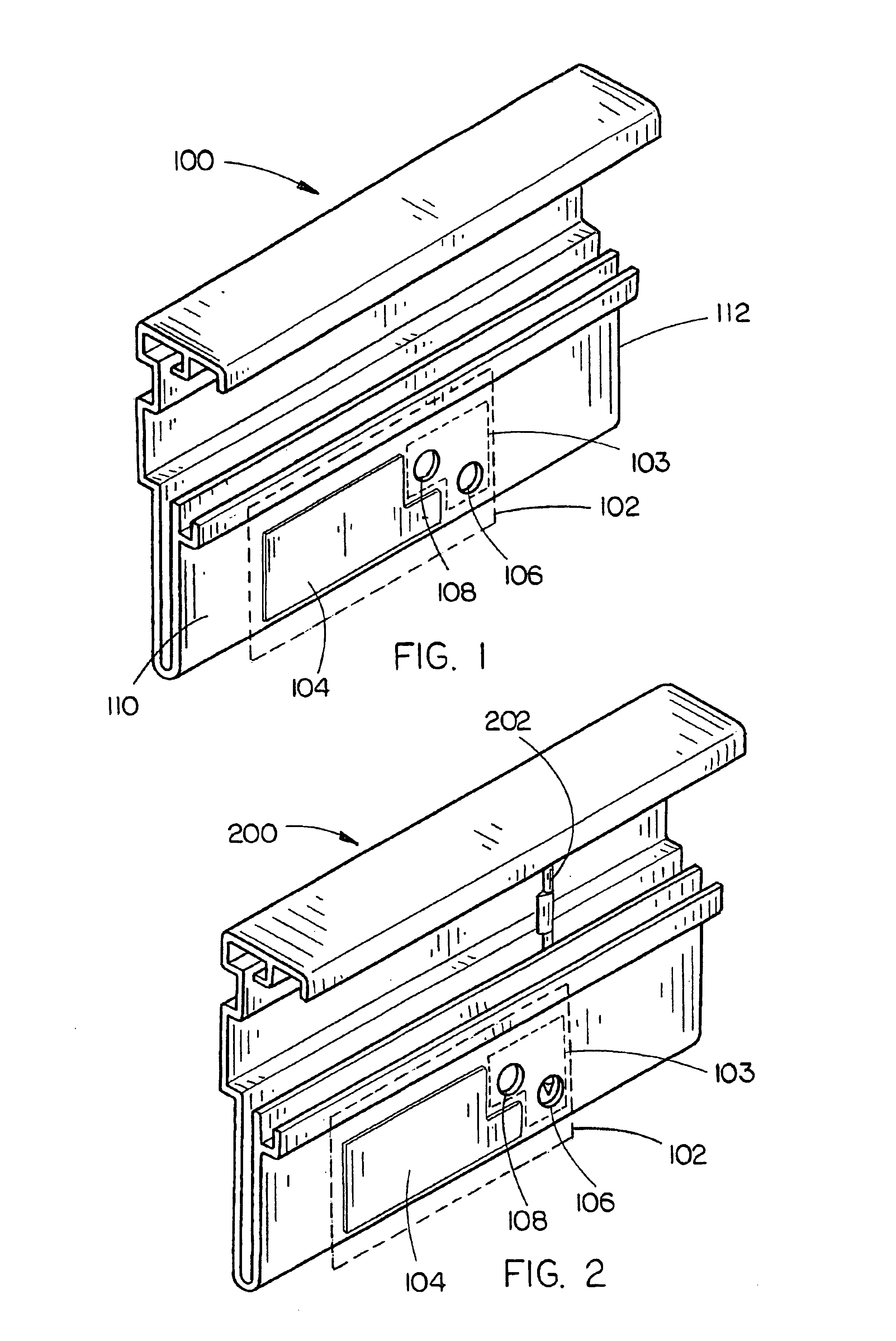
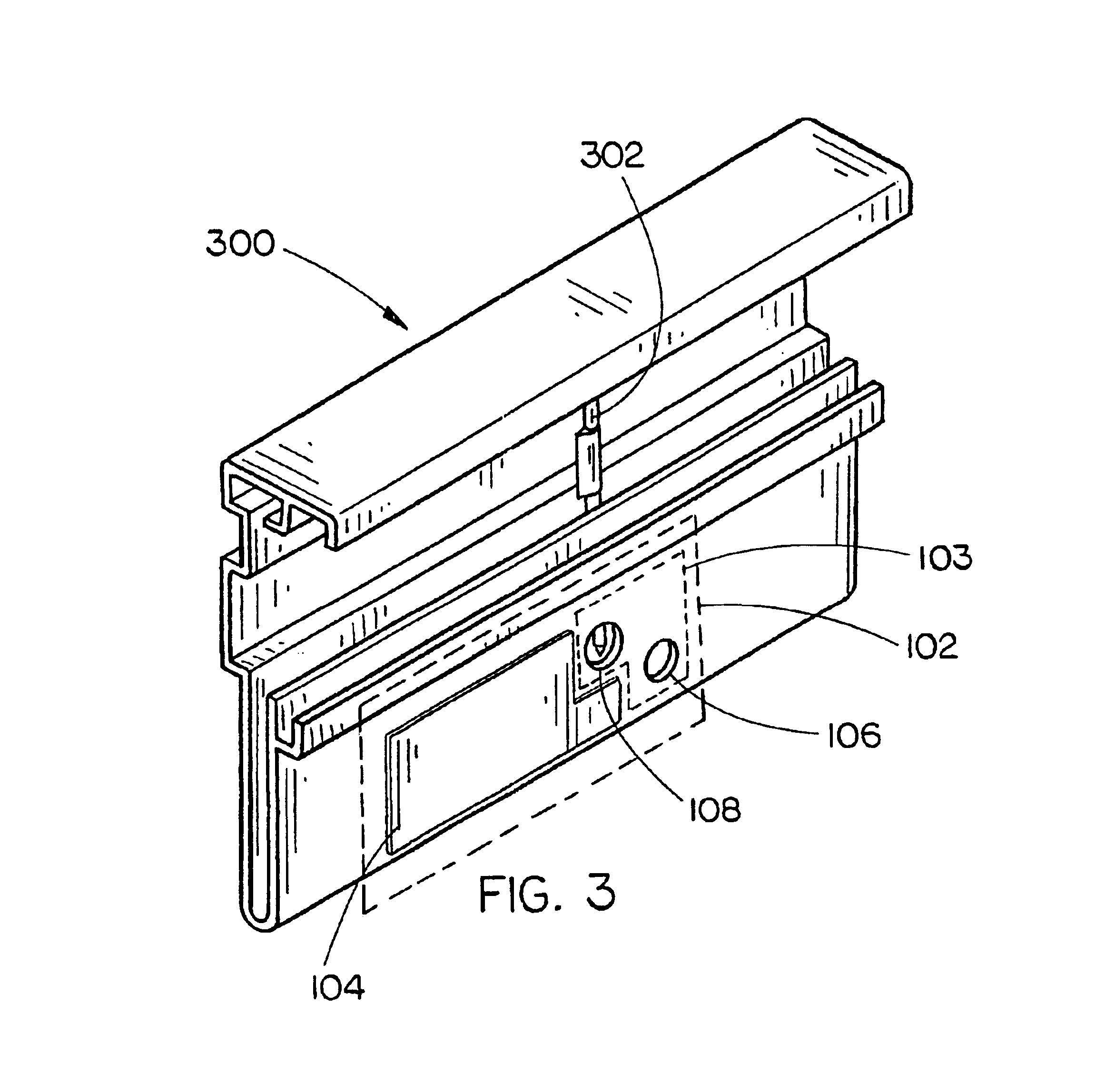
[0020]In a preferred embodiment, shown in FIG. 1, a housing 100 is provided with a compressor pressure indication assembly 102 in accordance with the present invention. The compressor pressure indication assembly 102 includes a readout assembly 104 and a nail verification assembly 103. Preferably, ...


PUM

PropertyMeasurementUnit
pressureaaaaaaaaaa
lengthaaaaaaaaaa
diameteraaaaaaaaaa

Abstract

An apparatus which enables a user of a pneumatic tool device, such as a nail gun, to determine the required compressor pressure needed to most effectively utilize the pneumatic tool device and maximize the life of the tool. A compressor pressure indication assembly on a nail gun comprising a nail verification assembly and a readout assembly enables a user to verify the length and / or diameter of the nails to be driven by the nail gun and set the compressor pressure accordingly.

Description

CROSS REFERENCE TO RELATED APPLICATION[0001]The present application claims priority under 35 U.S.C. §119 to the U.S. Provisional Application Ser. No. 60 / 422,378 filed on Oct. 30, 2002 which is herein incorporated by reference in its entirety.FIELD OF THE INVENTION[0002]The present invention generally relates to the field of pneumatic tool devices, and particularly to an apparatus and method for indicating the required compressor pressure to be used when operating a pneumatic tool, such as a pneumatic nail gun.BACKGROUND OF THE INVENTION[0003]The use of air driven tools is commonplace in a variety of construction situations. Pneumatic nail guns have greatly increased efficiency and productivity on construction worksites. However, nail guns which employ air pressure (pneumatic nail guns) to drive nails have a limited life span due to the high pressures involved in their use. This may result in inefficient tool functionality which may increase labor time and construction costs. Further...

Claims


Application Information

Patent Timeline
Patent Type & Authority Patents(United States)
IPC IPC(8): B25C1/00B25C5/00B25C1/04B25C5/16
CPCB25C1/005B25C5/1658B25C1/047Y10T29/49826
Inventor BEVILLE, JOHN M.
Owner BLACK & DECKER INC
Why Eureka
Try Eureka