Switchover mechanism for a reversible control valve of a pneumatic tool

a technology of reversible control valve and switchover mechanism, which is applied in the field of pneumatic tools, can solve the problems of inability to achieve, difficulty and inconvenience, and still has the existing difficulty of “switching” and achieve the effect of convenient and fast switching, convenient and practical

Active Publication Date: 2007-01-18
BASSO IND CORP
View PDF10 Cites 31 Cited by
  • Summary
  • Abstract
  • Description
  • Claims
  • Application Information

AI Technical Summary

Benefits of technology

[0010] The issue disclosed in the previous section mentioned that the parts of the switchover bar of the reversible control valve of the pneumatic tool must be taken apart completely before it can switch because of the users' right handedness and left-handedness. In comparison, the connecting section 21 of the switchover bar 20 of the present invention can be solved by using the positioning or releasing of the combination of the combination and position section 23 and the valve bar positioning section 14 of the reversible control valve 10, and further using the repositioning function for the elastic component 60 and speed-adjusting valve 30 that coordinate with the outward movement of the switchover bar 20 to make the switching of the toggle switch 22 of the switchover bar 20 easier and faster without having to take the parts apart, and without assisting tools. For the industry and users, it makes the switching more convenient and practical.

Problems solved by technology

Because the switch mechanism for the reversible control valve of today's pneumatic tool has not considered the need mentioned above, it still has the existing “switching” difficulty.
Therefore, when the switchover control needs to be adjusted to the relative angle due to the demand of “switching” mentioned above, because it is connected to other components, it cannot be achieved.
Thus, this conventional structure is time consuming for switching the switchover control, and for the user that does not have the assisting tool, it becomes difficult and inconvenient when the circumstances of right handed and left-handed users occur.

Method used


Image

  • Switchover mechanism for a reversible control valve of a pneumatic tool
  • Switchover mechanism for a reversible control valve of a pneumatic tool
  • Switchover mechanism for a reversible control valve of a pneumatic tool

Examples


Embodiment Construction

[0026] The features and the advantages of the present invention will be more readily understood upon a thoughtful deliberation of the following detailed description of a preferred embodiment of the present invention with reference to the accompanying drawings.

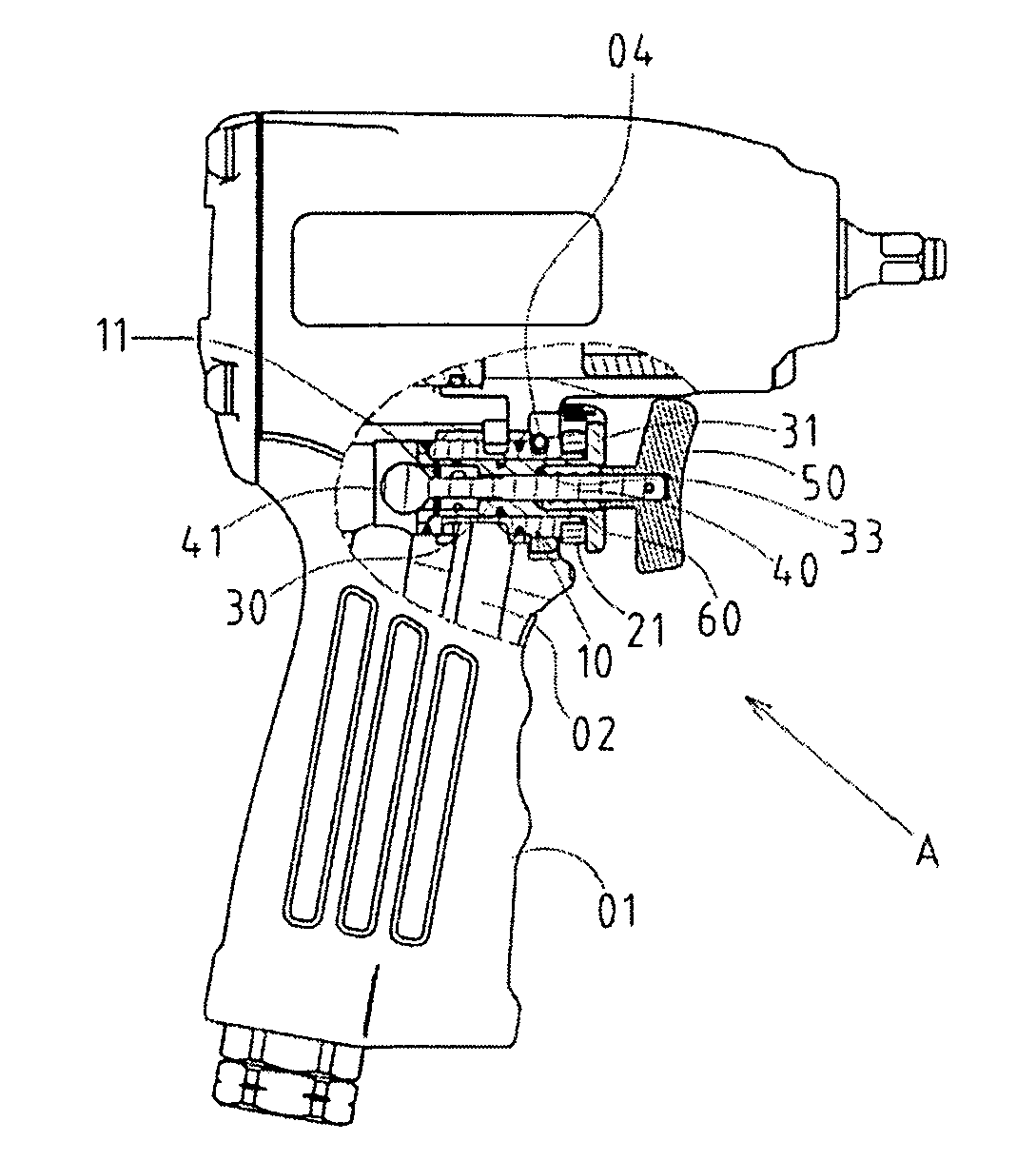
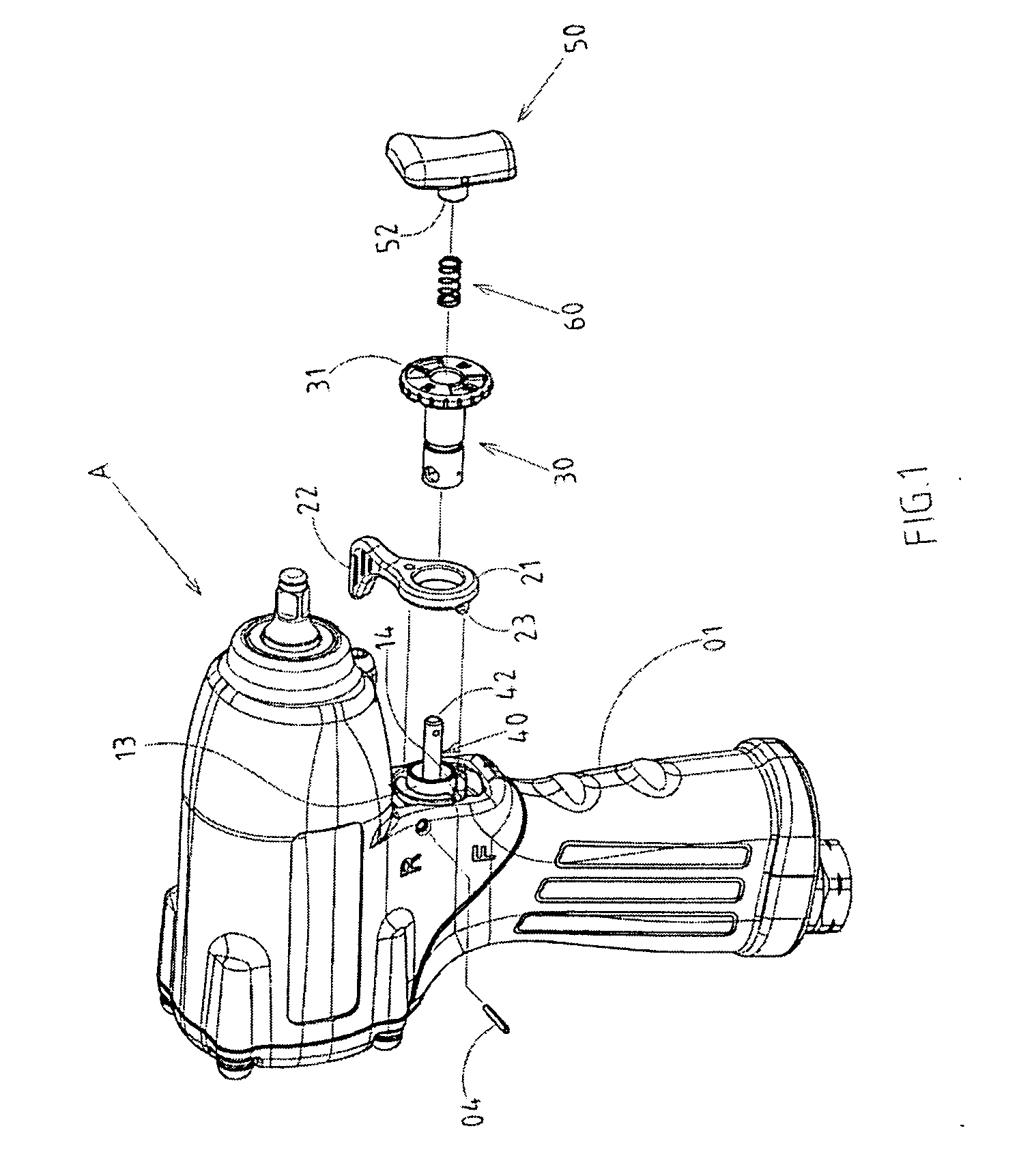
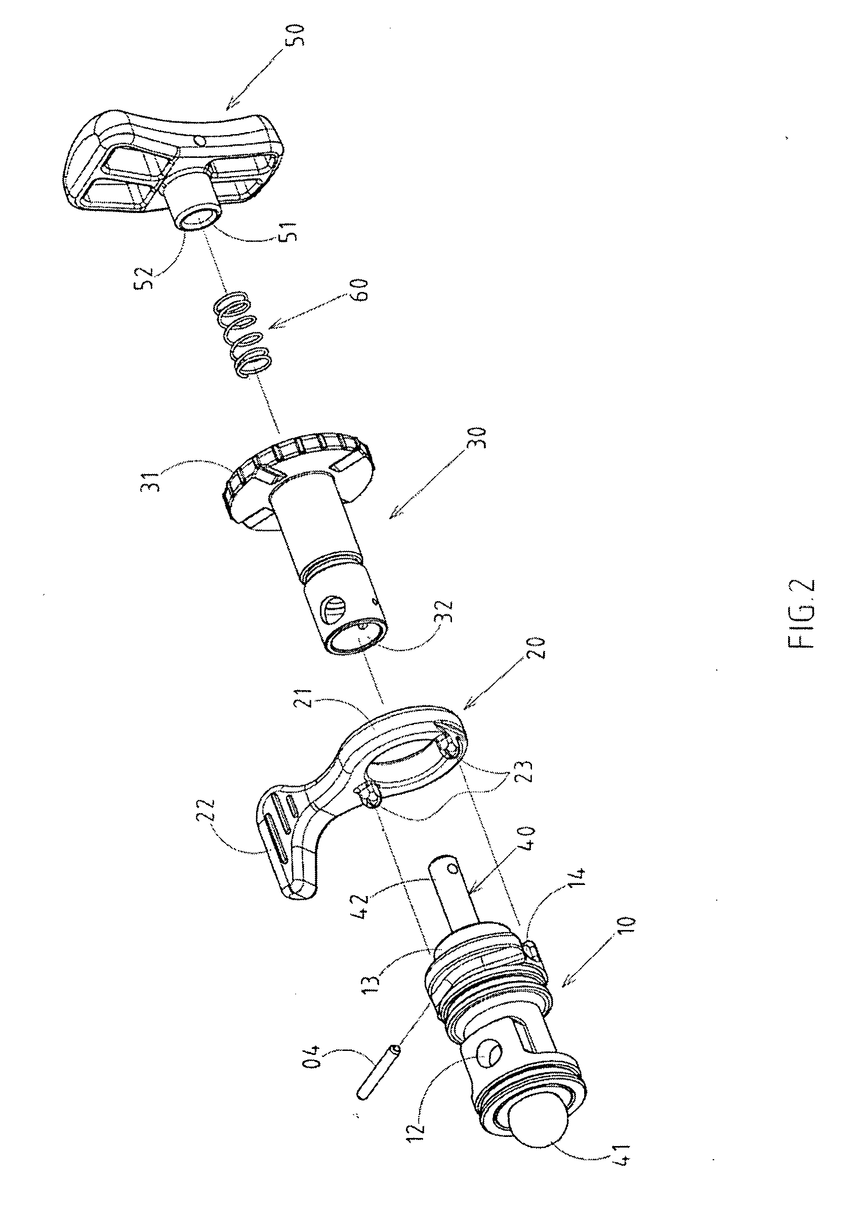
[0027] As shown in FIGS. 1-4, a switchover mechanism for the reversible control valve of a pneumatic tool, in which a pneumatic tool (A) is a pneumatic handle. The purpose for the reversible control valve is to be able to reverse the switch for the switchover bar without having to take of the reversible control valve, so that it can quickly be change to left-handed mode or right handed mode.

[0028] The invention includes a reversible control valve 10, which is a hollow cylinder that has a through slit 11 in the center, and it is placed in the horizontal slot 01 (as shown in FIG. 5) on the air inlet channel 02 of the handle 01 of the pneumatic tool A. However, the direction of its axle is positioned by using a bolt 04 bolted ho...


PUM

PropertyMeasurementUnit
angleaaaaaaaaaa
areaaaaaaaaaaa
relative angleaaaaaaaaaa

Abstract

The switch mechanism for the reversible control valve of the pneumatic tool focuses on the switchover bar because of the users' right handed and left-handed issues. The primary feature is to make the switchover bar of the reversible control valve and the speed-adjusting valve to roll in the axial direction, and use the combination of the elastic component to make the combination and position section of the connecting section to position with the valve bar positioning section of the reversible control valve. When force of the connecting section of the switchover bar is pulled toward external trigger, it can release the combination and position section and the toggle switch of the switchover bar can achieve switching. When the toggle switch is adjusted, the repositioning may be restored by using the combination and position section and valve bar positioning section without having to take the parts apart.

Description

RELATED U.S. APPLICATIONS [0001] Not applicable. STATEMENT REGARDING FEDERALLY SPONSORED RESEARCH OR DEVELOPMENT [0002] Not applicable. REFERENCE TO MICROFICHE APPENDIX [0003] Not applicable. FIELD OF THE INVENTION [0004] The present invention relates generally to a pneumatic tool, and more particularly to a device that has a switchover mechanism for a reversible control valve. BACKGROUND OF THE INVENTION [0005] Because a common pneumatic tool, such as a pneumatic handle, has a difference between tightening the screws and loosening the screws when in use, the tool reacts to the direction the pneumatic tool turns, which is tightening when turning clockwise, and loosening when turning counterclockwise. Because it must have these two functions, the structure of the pneumatic tool must have a switch design that has reversible control, and usually this is achieved by placing a reversible control. Moreover, a switchover control must be placed on the outside of the pneumatic tool and conne...

Claims


Application Information

Patent Timeline
Patent Type & Authority Applications(United States)
IPC IPC(8): B26B7/00
CPCB25B21/00
Inventor HUA, CHIANGLIN, MING-CHUAN
Owner BASSO IND CORP
Why Eureka
Try Eureka