Pneumatic tool

a technology of pneumatic tools and pneumatic exhausts, which is applied in the field of pneumatic tools, can solve problems such as accidents and wrong actions, and achieve the effect of reducing the noise of pressurized air and smooth exhausting of pressurized air

Inactive Publication Date: 2006-01-31
HYPHONE MASCH IND CO LTD
View PDF11 Cites 29 Cited by
  • Summary
  • Abstract
  • Description
  • Claims
  • Application Information

AI Technical Summary

Benefits of technology

[0007]The primary advantage of the pneumatic tool of the present invention is that it smoothly

Problems solved by technology

Some of the pressurized air is retained in the shell 91 so t

Method used


Image

  • Pneumatic tool
  • Pneumatic tool
  • Pneumatic tool

Examples


first embodiment

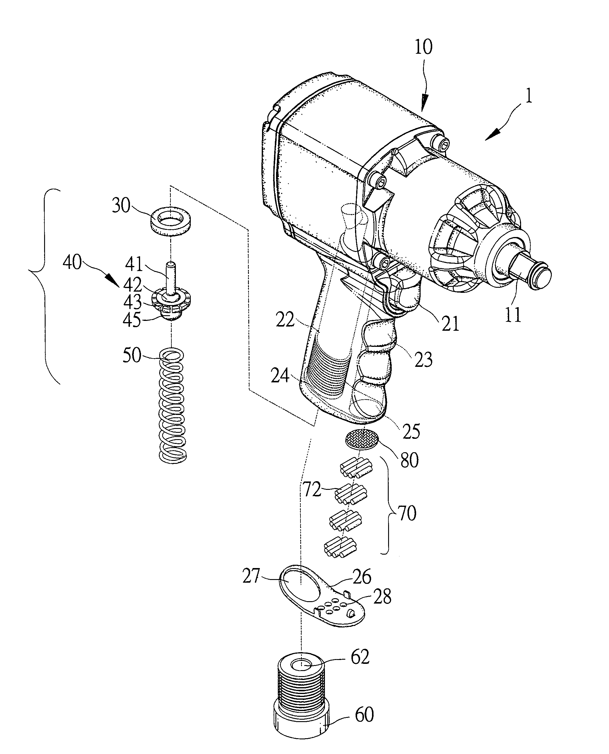
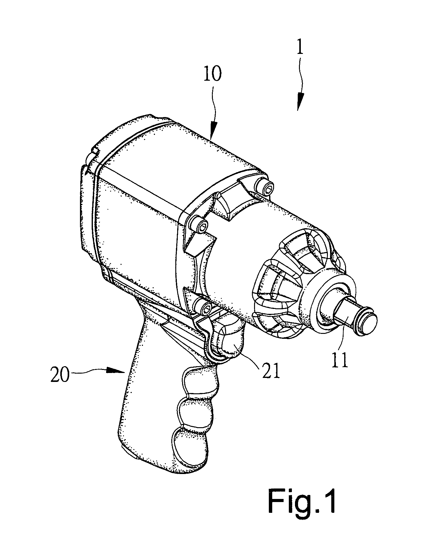
[0017]FIG. 1 shows a pneumatic tool 1 according to the present invention. The pneumatic tool 1 includes a shell consisting of a barrel 10 and a handle 20 extending from the barrel 10.

[0018]Referring to FIGS. 2 and 3, the pneumatic tool 1 includes a rotor 12 installed in a chamber 16 defined in the barrel 10. A shaft 14 is connected with the rotor 12 in a co-axial manner. The shaft 14 includes a driving tip 11 exposed to the exterior of the barrel 10. A socket (not shown) can be engaged with the driving tip 11.

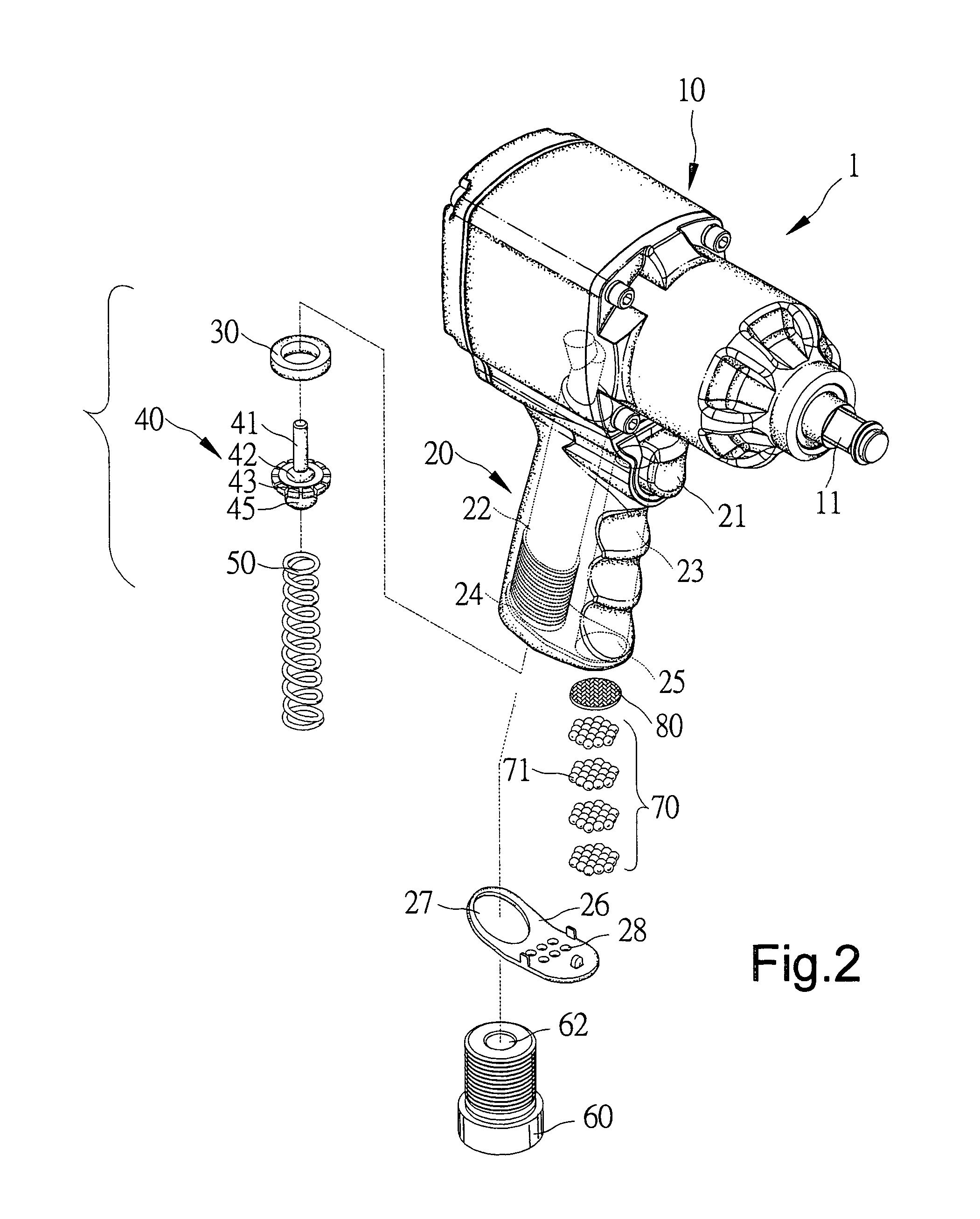
[0019]The handle 20 includes a first passage 22 communicated with the chamber 16 and a second passage 23 communicated with the chamber 16. The first passage 22 includes an entrance 24. The second passage 23 includes an exit 25.

[0020]A control device is put in the first passage 22. The control device includes a washer 30, a valve 40 and a spring 50. The valve 40 includes a disc 42, a rod 41 extending from the disc 42 in a direction and a tongue 45 extending from the disc 42 in a...

second embodiment

[0028]The pneumatic tool according to the first or second embodiment of the present invention smoothly exhausts the pressurized air and efficiently reduces the noises that the pressurized air makes.


PUM


Abstract

A pneumatic tool includes a shell with a chamber defined therein, a first passage communicated with the chamber and a second passage communicated with the chamber. A rotor is installed in the chamber for rotation when driven by pressurized air flowing into the chamber through the first passage. A shaft extends to the exterior of the shell from the rotor. A trigger is installed on the shell. A control device is put in the first passage and connected with the trigger for controlling the first passage. A muffler is put in the second passage. The muffler includes a plurality of balls.

Description

BACKGROUND OF INVENTION[0001]1. Field of Invention[0002]The present invention relates to a pneumatic tool.[0003]2. Related Prior Art[0004]Referring to FIG. 7, a typical pneumatic tool 90 includes a shell 91 defining a working space, a first passage 92 and a second passage 93. Although not shown, a core is put in the working space of the shell 91. Pressurized air flows into the working space from a pump (not shown) through the first passage 92. The pressurized air flows to the exterior of the shell 91 from the working space through the second passage 93. The core is rotated by the pressurized air in the working space. A muffler 94 is fit in the second passage 93. The muffler 94 defines a plurality of gaps (not numbered) through which the pressurized air flows. The gaps defined in the muffler 94 are very small. Thus, the pressurized air is not completely exhausted through the muffler 94. Some of the pressurized air is retained in the shell 91 so that it often causes wrong actions and ...

Claims


Application Information

Patent Timeline
IPC IPC(8): B23B45/04B21J1/00
CPCB25F5/00F01N1/081Y10S173/02
Inventor CHEN, TING-YUAN
Owner HYPHONE MASCH IND CO LTD
Why Eureka
Try Eureka