Pneumatic Pressure Output Control by Drive Valve Duty Cycle Calibration

a technology of drive valve and output control, applied in the field of calibration, can solve the problems of operating pressure loss, open and closed operating pressure above a predetermined threshold,

Active Publication Date: 2011-03-03
ALCON INC
View PDF99 Cites 32 Cited by
  • Summary
  • Abstract
  • Description
  • Claims
  • Application Information

AI Technical Summary

Benefits of technology

[0011]In various embodiments, a surgical console may include a pneumatic valve (e.g., a four way solenoid valve) with at least two ports operable to alternately provide pressurized gas to drive a pneumatic tool (such as a vitrectomy probe) coupled to the surgical console. The surgical console may further include a controller operable to control and adjust the valve open / close times according to a valve duty cycle. The valve may switch between ports (valve open time for a first port and valve close time for a second port) such that a total valve time may approximately equal the valve open time plus the valve close time. The valve duty cycle may indicate a percentage (e.g., 50%) of the total valve time for the controller to signal the valve to open.
[0012]Because different valve open / close timings can lead to a loss in operating pressure, an adjustment may be made to the valve duty cycle so that signal timing for the open and / or closed valve positions will result in open and closed operating pressures above a predetermined threshold. For example, the adjusted valve duty cycle may be approximately equal to a previous valve duty cycle+(((abs(open pressure)−abs(closed pressure)) / 2)*(valve duty cycle delta / differential pressure change delta)) where the previous valve duty cycle is the valve duty cycle during testing, open pressure and closed pressure are differential pressures for the ports at respective open and closed times during one cycle of the valve, and the valve duty cycle delta / differential pressure change delta is a ratio of valve duty cycle change to resulting differential pressure change (for example, in the valve open pressure). For calculating the new valve duty cycle, the open pressure and closed pressure for the port may be taken during a lowest performance point for the pneumatic system (e.g., when the absolute pressure difference between the open pressure and closed pressure is the lowest such that (abs(open pressure)+abs(closed pressure)) is at a minimum for the measured pressure data). Once determined, the valve duty cycle may be stored on a memory accessible by the controller for future use.
[0013]In some embodiments, a valve duty cycle may be input into the system through a series of DIP switch settings. For example, the surgical console may include DIP switches and resistors coupled together such that the DIP switches are configurable to combine one or more of the resistors in a resistor network. The DIP switches may be set such that upon applying an input voltage to the resistor network, an output voltage of the resistor network is indicative of a valve duty cycle. In some embodiments, the surgical console may include an analog to digital converter operable to convert the output voltage to a digital value that software executing on the surgical console can use to determine a valve duty cycle (e.g., through the use of a look-up table that associates the digital value with an associated valve duty cycle).

Problems solved by technology

Because different valve open / close timings can lead to a loss in operating pressure, an adjustment may be made to the valve duty cycle so that signal timing for the open and / or closed valve positions will result in open and closed operating pressures above a predetermined threshold.

Method used


Image

  • Pneumatic Pressure Output Control by Drive Valve Duty Cycle Calibration
  • Pneumatic Pressure Output Control by Drive Valve Duty Cycle Calibration
  • Pneumatic Pressure Output Control by Drive Valve Duty Cycle Calibration

Examples


Embodiment Construction

[0024]U.S. Patent Application Publication entitled “Pneumatic System for a Vitrector,” Publication No. 20080149197, Ser. No. 11 / 614,678, by Denis Turner, Robert Palino, Argelio Olivera, and Mark Hopkins filed Dec. 21, 2006 is hereby incorporated by reference in its entirety as though fully and completely set forth herein.

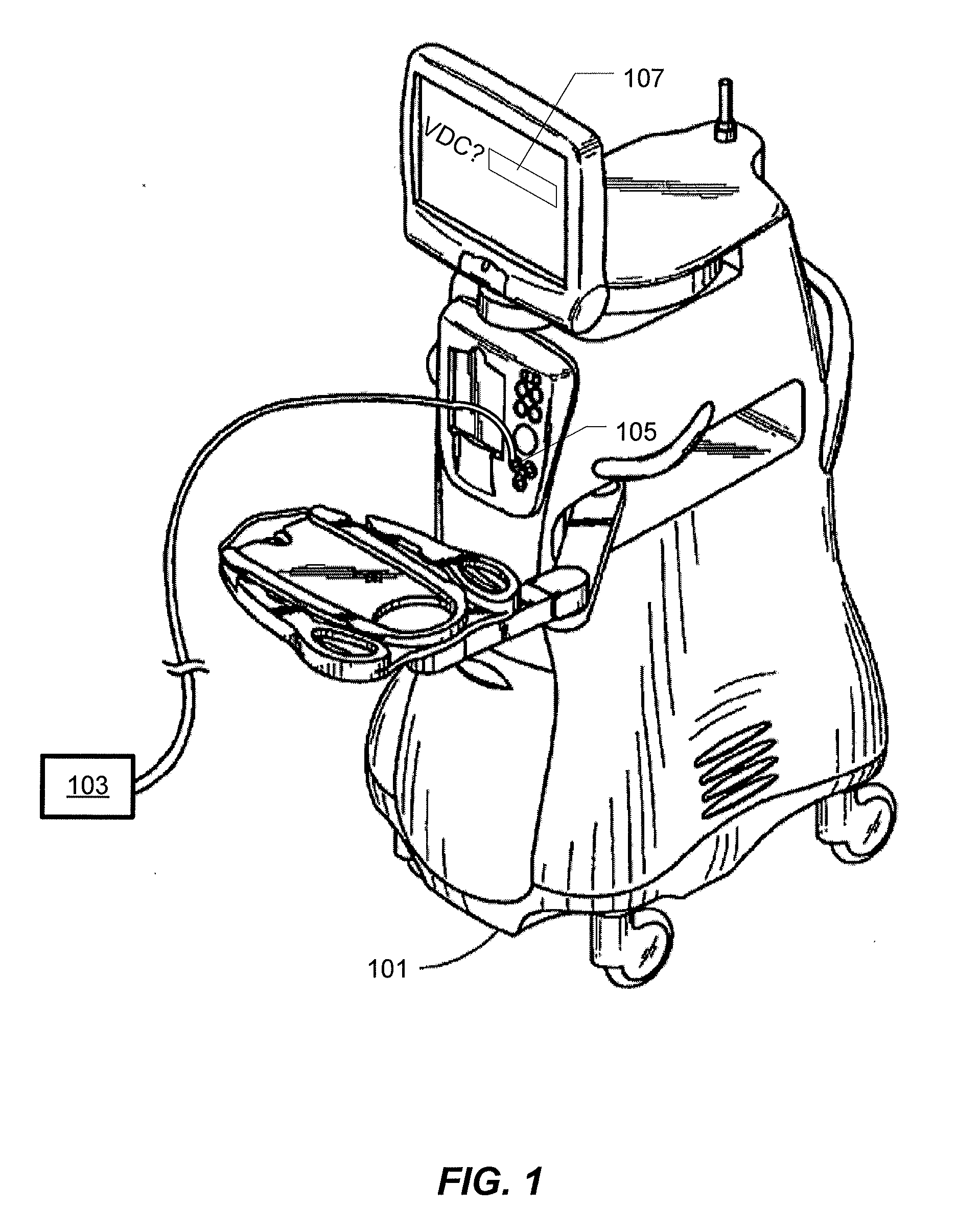
[0025]FIG. 1 illustrates an embodiment of a surgical console 101 for a pneumatically powered ophthalmic surgical machine. The surgical console 101 may operate to assist a surgeon in performing various ophthalmic surgical procedures, such as phacoemulsification and vitrectomy. The surgical console 101 may include an internal monitor system, one or more controllers (e.g., proportional controllers), and tools (which may include phacoemulsification tools and / or pneumatic tools 103). The pneumatic tools 103 may include, for example, scissors, vitrectors, forceps, and injection or extraction modules. Other tools 103 may also be used. A compressed gas, such as nitrogen, ma...


PUM

PropertyMeasurementUnit
total transition timeaaaaaaaaaa

Abstract

In various embodiments, a surgical console may include a pneumatic valve to drive a pneumatic tool coupled to the surgical console. The console may further include a controller operable to control and adjust the valve open/close cycle times according to a valve duty cycle. The valve may switch between ports (valve open time for a first port and valve close time for a second port) such that a total valve time may approximately equal the valve open time plus the valve close time. The valve duty cycle may indicate a percentage of the total valve time for the controller to signal the valve to open and may include an adjustment that corresponds to a signal timing of the open and/or closed valve positions that will result in open and closed operating pressures above a predetermined threshold.

Description

PRIORITY CLAIM[0001]This application claims the benefit of priority of U.S. Provisional Patent Application Ser. No. 61 / 238,431 titled “Pneumatic Pressure Output Control By Drive Valve Duty Cycle Calibration”, filed on Aug. 31, 2009, whose inventors are Jiansheng Zhou, Kurt Leukanech, and Dan Teodorescu, which is hereby incorporated by reference in its entirety as though fully and completely set forth herein.FIELD OF THE INVENTION[0002]The present invention generally pertains to calibration. More particularly, but not by way of limitation, the present invention pertains to calibration for a pneumatic surgical system.DESCRIPTION OF THE RELATED ART[0003]Vitreo-retinal procedures include a variety of surgical procedures performed to restore, preserve, and enhance vision. Vitreo-retinal procedures are appropriate to treat many serious conditions of the back of the eye. Vitreo-retinal procedures treat conditions such as age-related macular degeneration (AMD), diabetic retinopathy and diab...

Claims


Application Information

Patent Timeline
Patent Type & Authority Applications(United States)
IPC IPC(8): A61F9/007A61B17/00G01L7/00
CPCA61B2017/00154A61B2017/00176A61B19/56A61B2017/00544A61F9/00763A61B2017/00181A61B34/25Y10T83/8858
Inventor ZHOU, JIANSHENGLEUKANECH, KURT D.TEODORESCU, DAN
Owner ALCON INC
Why Eureka
Try Eureka