Gravity compensation device

A technology of gravity compensation and air chamber, which is applied in the direction of photolithography exposure device, microlithography exposure equipment, spring/shock absorber, etc., can solve the problems of rigid spring static position deviation, increased use cost, high cost, etc., to achieve Effects of reducing resonance, eliminating errors, and simple structure

Active Publication Date: 2012-06-06
SHANGHAI MICRO ELECTRONICS EQUIP (GRP) CO LTD
View PDF10 Cites 30 Cited by
  • Summary
  • Abstract
  • Description
  • Claims
  • Application Information

AI Technical Summary

Problems solved by technology

[0005] In the U.S. Patent No. US20050036126, a micro-motion table supported by steel springs is disclosed. The micro-motion table described in this patent has the following disadvantages: 1. The quality of the micro-motion table changes, causing the rigid spring to produce static Position offset; 2. In order to maintain the position stability of the micro-motion table, the steel spring has a relatively high stiffness, and the vibration of the base is easily transmitted to the micro-motion table; 3. The steel spring has no damping and is easy to excite resonance
[0006] In the U.S. Patent No. US6473161, a mic

Method used


Image

  • Gravity compensation device
  • Gravity compensation device
  • Gravity compensation device

Examples


specific Embodiment 1

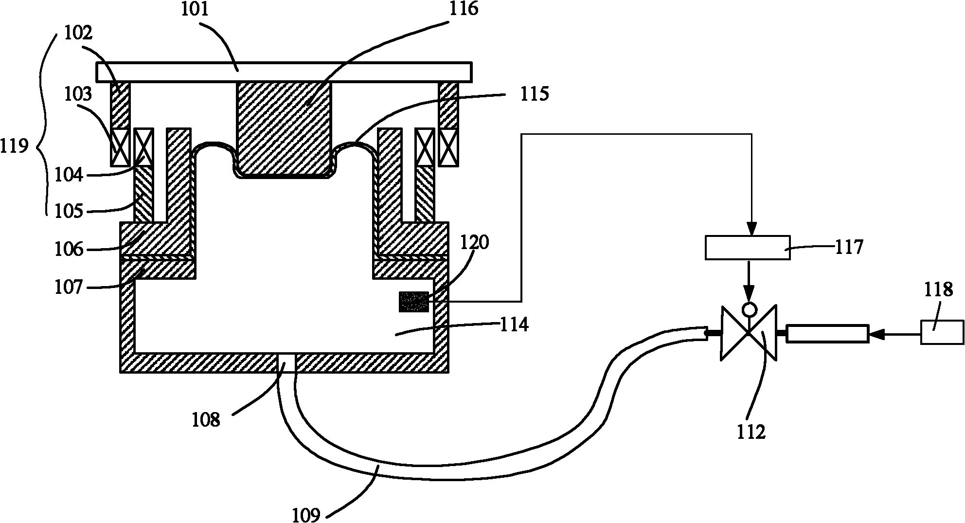
[0027] figure 1 It is a schematic structural diagram of the gravity compensation device in an embodiment of the present invention, please refer to figure 1 In combination with the above core idea, the present invention provides a gravity compensation device, which communicates with the air supply source 118 and includes the first air chamber shell 107, the bushing 106, the membrane structure 115, the piston 116, the support plate 101 and the pneumatic valve 112, wherein the bushing 106 is located above the first air chamber housing 107; the two ends of the membrane structure 115 are between the bushing 106 and the first air chamber housing 107, so that the membrane structure 115 and the first air chamber shell 107 form the first air chamber 114; the piston 116 is supported on the membrane structure 115; the support plate 101 is fixed above the piston 116; the pneumatic valve One end of 112 communicates with the gas path of the first air chamber 114 , and the other end communi...

specific Embodiment 2

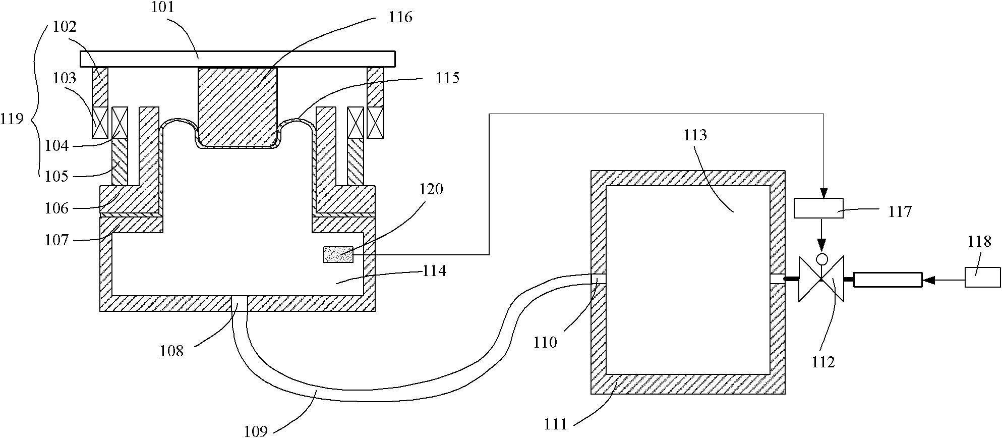
[0052] figure 2 It is a structural schematic diagram of the gravity compensation device in another embodiment of the present invention, please refer to figure 2 . On the basis of the first embodiment, a second air chamber 113 is added between the first air chamber 114 and the pneumatic valve 112 . The second air chamber 113 is sealed inside the second air chamber housing 111, and a second air chamber aperture 110 is arranged on the second air chamber housing 113, and the second air chamber aperture 110 is connected to the second air chamber housing 111. The first air chamber 114 communicates with the air path, and the second air chamber small hole 110 communicates with the first air chamber small hole 108 through a trachea. Preferably, the small hole in the second air chamber is a damping hole. The damping hole is designed so that the damping rate of the gravity compensation device is between 0.01 and 0.85, wherein preferably, the damping rate is 0.4-0.7. Within the abov...


PUM


Abstract

The invention discloses a gravity compensation device which is used for supporting a micropositioner of a worktable and a reticle stage in a photoetching machine and is communicated with a gas circuit of a gas supplying gas source. The gravity compensation device comprises a first gas chamber, a piston, a supporting plate and a pneumatic valve, wherein the piston is supported by the first gas chamber; the supporting plate is used for supporting the micropositioner, is positioned above the piston and is fixedly connected with the piston; and the valve is communicated with the first gas chamber and is used for adjusting the air pressure of the first air chamber. The gravity compensation device has the advantages that: firstly, the gravity compensation device has a simple structure; secondly, the gravity compensation device has lower rigidity so as to isolate low-frequency vibration; thirdly, the gravity compensation device has certain damping so as to reduce resonance; thirdly, the gravity compensation device has no action of exhausting gas to the environment and can be applied to a vacuum environment; and fourthly, when a load changes, the error of a static position of the reticle stage can be eliminated by adjusting the air pressure of the first gas chamber.

Description

technical field [0001] The invention relates to an integrated circuit manufacturing process equipment, in particular to a gravity compensation device. Background technique [0002] In the front-end manufacturing of large-scale semiconductor integrated circuits, photolithography is a very important process. It is a complex process that sequentially transfers chip patterns on a series of masks to corresponding layers of the wafer through an exposure system. The entire photolithography process consumes about 60% of the chip front-end manufacturing time, and accounts for nearly 40% of the cost of the entire chip manufacturing. This series of complex, expensive, and time-consuming lithography processes is concentrated on a group of lithography machines corresponding to the chip front-end production line, and the lithography machines are also the most complex and demanding equipment in the front-end manufacturing of semiconductor integrated circuits , the lithography machine inte...

Claims


Application Information

Patent Timeline
IPC IPC(8): F16F15/027G03F7/20
Inventor 廖飞红李小平朱岳彬
Owner SHANGHAI MICRO ELECTRONICS EQUIP (GRP) CO LTD
Why Eureka
Try Eureka