Digital imaging system using overlapping images to formulate a seamless composite image and implemented using either a digital imaging sensor array

a digital imaging and composite image technology, applied in the field of photographic image processing and reproduction, can solve the problems of image anomalies, image anomalies, and time slippage from left to right across the composite field of view, and achieve the effect of removing perspective errors

Inactive Publication Date: 2007-05-08
PANX IMAGING
View PDF46 Cites 103 Cited by
  • Summary
  • Abstract
  • Description
  • Claims
  • Application Information

AI Technical Summary

Benefits of technology

[0011]Another particular aspect of the present invention is a method of incorporating artificial intelligence through a complex neural network.

Problems solved by technology

This time slippage created image anomalies such as double images of moving objects within the multiple fields of view used to create the composite print or image.
The fundamental problem with this type of camera system is that it creates time slippage from left to right across the composite field of view.
The primary problem with this camera system is that the 360 degree image app

Method used


Image

  • Digital imaging system using overlapping images to formulate a seamless composite image and implemented using either a digital imaging sensor array
  • Digital imaging system using overlapping images to formulate a seamless composite image and implemented using either a digital imaging sensor array
  • Digital imaging system using overlapping images to formulate a seamless composite image and implemented using either a digital imaging sensor array

Examples


first embodiment

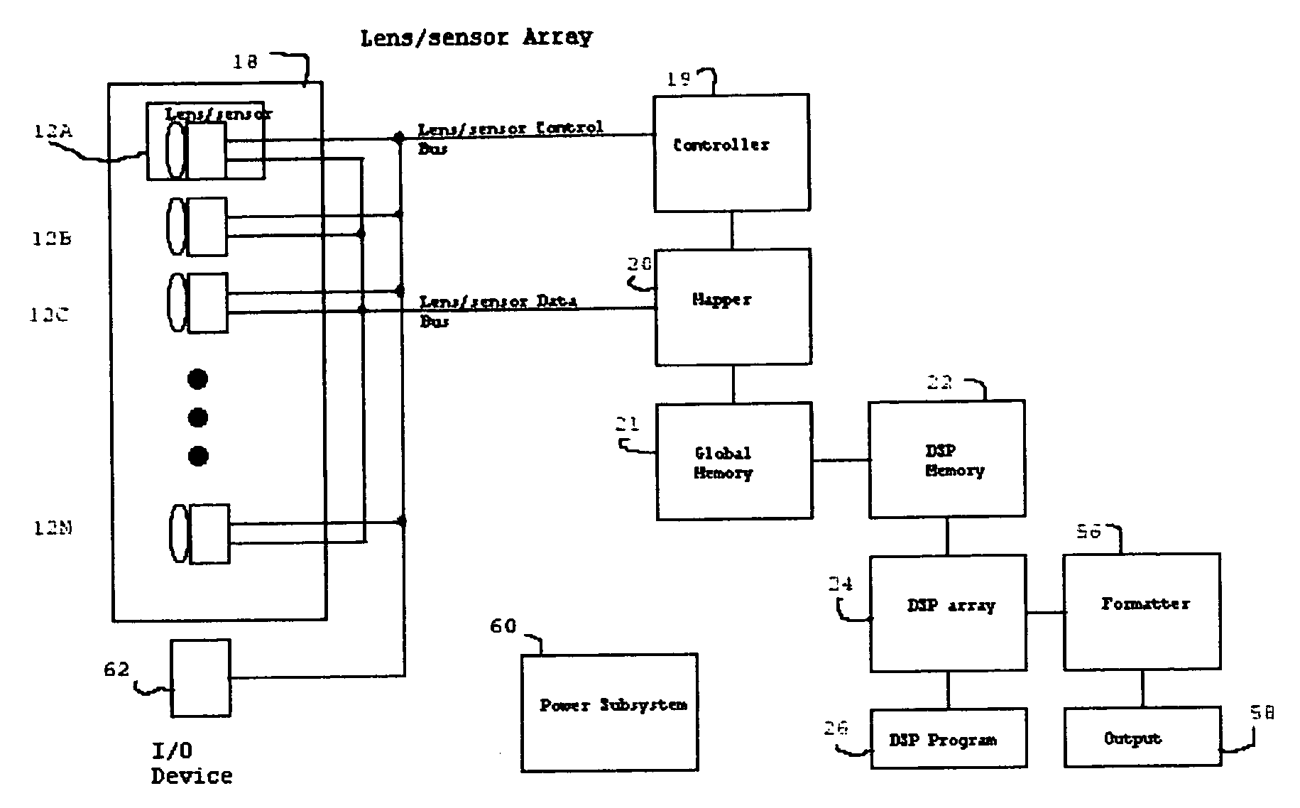
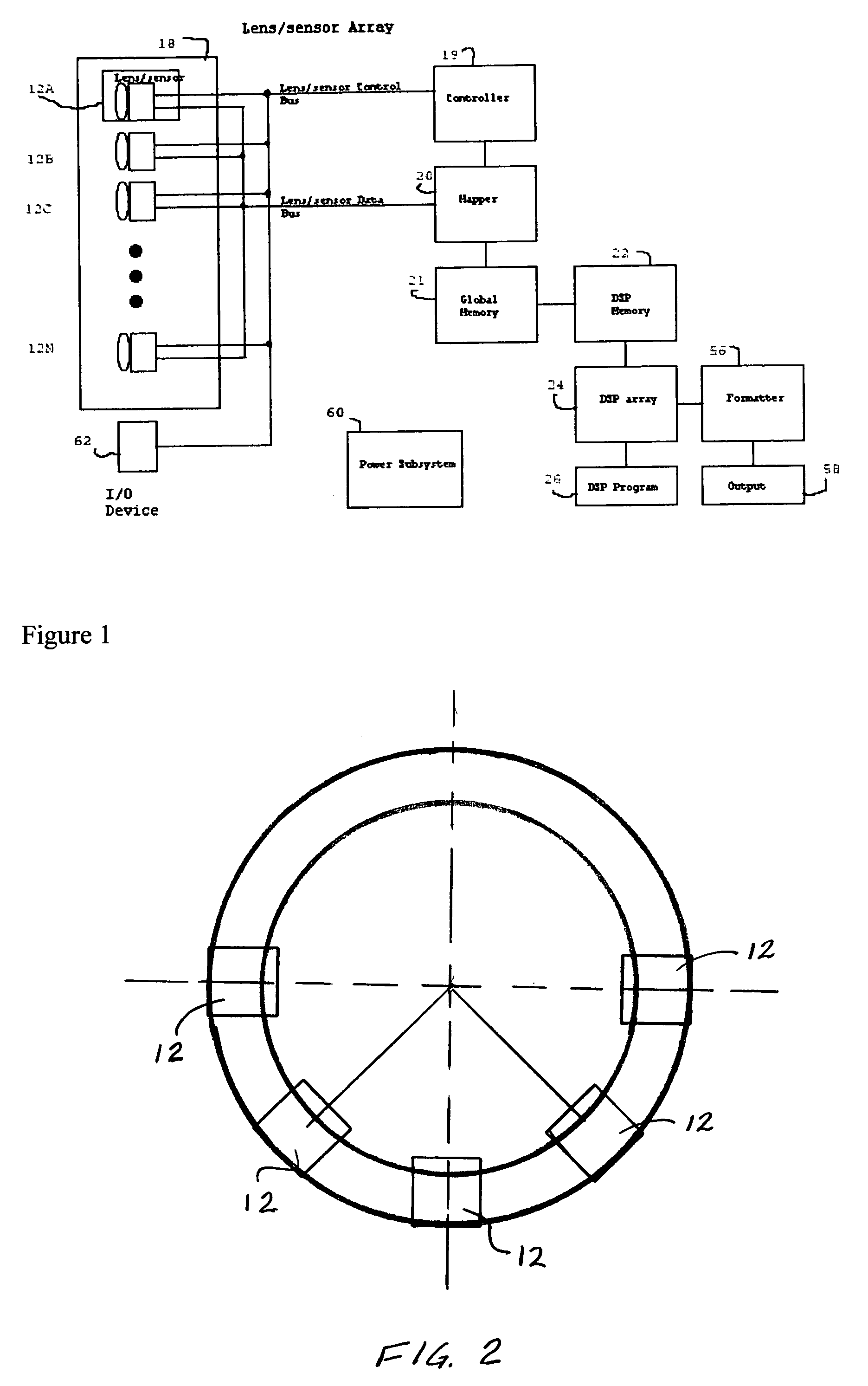
[0025]In another embodiment, the array 18 uses nine Kodak DX-4900 cameras with each camera corresponding to one of the lens / sensors 12. In this embodiment, the camera lens are positioned in a geometry such that each lens / sensor 12 is placed equidistance from a central point and aligned perpendicularly to a radius from such point such that the subtended angle between each lens / sensor 12 is 22.5 degrees. As in the first embodiment, power is supplied using a common 6.3 volt lead-acid battery and individual voltage regulators for each camera. The controller 19 includes additional switching functions for controlling the additional ones of the camera 12 in response to image capture commands from relay activation module 62. In both embodiments, the modification of the cameras to connect the focus and capture controls to controller 19 will be apparent to those ordinarily skilled in the art.

[0026]While the invention as described with reference to FIG. 1 utilizes a plurality of separate camer...

second embodiment

[0068]Near-field objects are then translated to composite image without correction. Finally, the pixel data (objects) are interpolated as required. This does imply that the outer pixels have less resolution than the inner pixels. It also implies that, in order to maintain rectangular coordinates there is not necessarily a 1:1 mapping of pixels. Pixels are, in essence, created through interpolation or removed through averaging. The compromise between pixel density and perspective error is aided by creating images with a very large number of pixels / square area. The second embodiment using lens / sensors from a Kodak DX-4900, for example, has 4.1 million pixels for a 35 mm equivalent. In this manner the oversampling interpolation (pixel creation) and undersampling (pixel averaging) is done with minimal informational loss in the result. Note that when an object is only in one image, the object is indeterminant and is defaulted to be the estimate of the closest known object that is bi-loca...


PUM


Abstract

An imaging system for obtaining a wide field of view comprises a plurality of imaging devices each having a defined field of view and each of the imaging devices having a mechanism for capturing an image at a selected time instant. The imaging devices are positioned such that the field of view of each device overlaps the field of view of each adjacent device. A control module simultaneously actuates each of the imaging devices to capturing an image within the field of view of all devices concurrently. The resulting images from each of the devices are merged to produce a wide field of view image.

Description

[0001]This application claims the benefit of U.S. Provisional Application No. 60 / 371,608, filed Apr. 10, 2002.FIELD OF THE INVENTION[0002]The present invention relates to photographic image processing and reproduction and, more particularly, to a method and apparatus for creating composite, wide angle images.BACKGROUND OF THE INVENTION[0003]It has been recorded that as early as the 1880's the idea of including more of an image on a print than what was available from a lens was attempted. The early inventions moved the camera as well as the film to allow synchronization with the field of view. The result was a developed film that contained a 360 degree (or less) image. The left part of the print was taken earlier than the right part of the print. This time slippage created image anomalies such as double images of moving objects within the multiple fields of view used to create the composite print or image.[0004]As technology progressed, the same type of wide view camera, referred to ...

Claims


Application Information

Patent Timeline
IPC IPC(8): H04N5/225G06K9/36G03B19/00H04N5/232H04N5/262
CPCG03B19/00H04N5/2259H04N5/232H04N5/23238H04N5/247H04N5/2624H04N5/2627H04N23/58H04N23/60H04N23/698H04N23/90
Inventor WACHTEL, ROBERT A.KEABLE, JOHNPAULSON, RICHARD
Owner PANX IMAGING
Why Eureka
Try Eureka