Mapping techniques using probe vehicles

a technology of mapping techniques and probe vehicles, applied in the direction of navigation instruments, instruments, images, etc., can solve the problems of increasing the complexity of the device design, adding cost and complexity to the design of accelerometer and sensor software, and affecting the accuracy of the data, etc., to achieve the effect of easy retrofit application

Active Publication Date: 2015-05-07
INTELLIGENT TECH INT
View PDF4 Cites 109 Cited by
  • Summary
  • Abstract
  • Description
  • Claims
  • Application Information

AI Technical Summary

Benefits of technology

[0008]In order to achieve a new and improved method and arrangement for creating maps of terrain surrounding and/or including roads, a method and system for mapping terrain including one or more roads in accordance with the invention includes a vehicle equipped with at least one camera, a position determining system that determines its position and an inertial measurement unit (IMU) that provides, when corrected by readings from the position determining system, the position and angular orientation of the camera(s) and IMU, all of which are in a set configuration relative to one another. A processor at a remote location apart from the vehicle receives data from the vehicle and converts information related to fiduciaries from the...

Problems solved by technology

The silicon crystal typically has residual stresses that can cause the mechanical structure of the accelerometer to change geometrically as a function of time and/or temperature unpredictably.
This adds cost and complexity to the accelerometer and sensor software design.
This self-testing feature also ...

Method used


Image

  • Mapping techniques using probe vehicles
  • Mapping techniques using probe vehicles
  • Mapping techniques using probe vehicles

Examples


Embodiment Construction

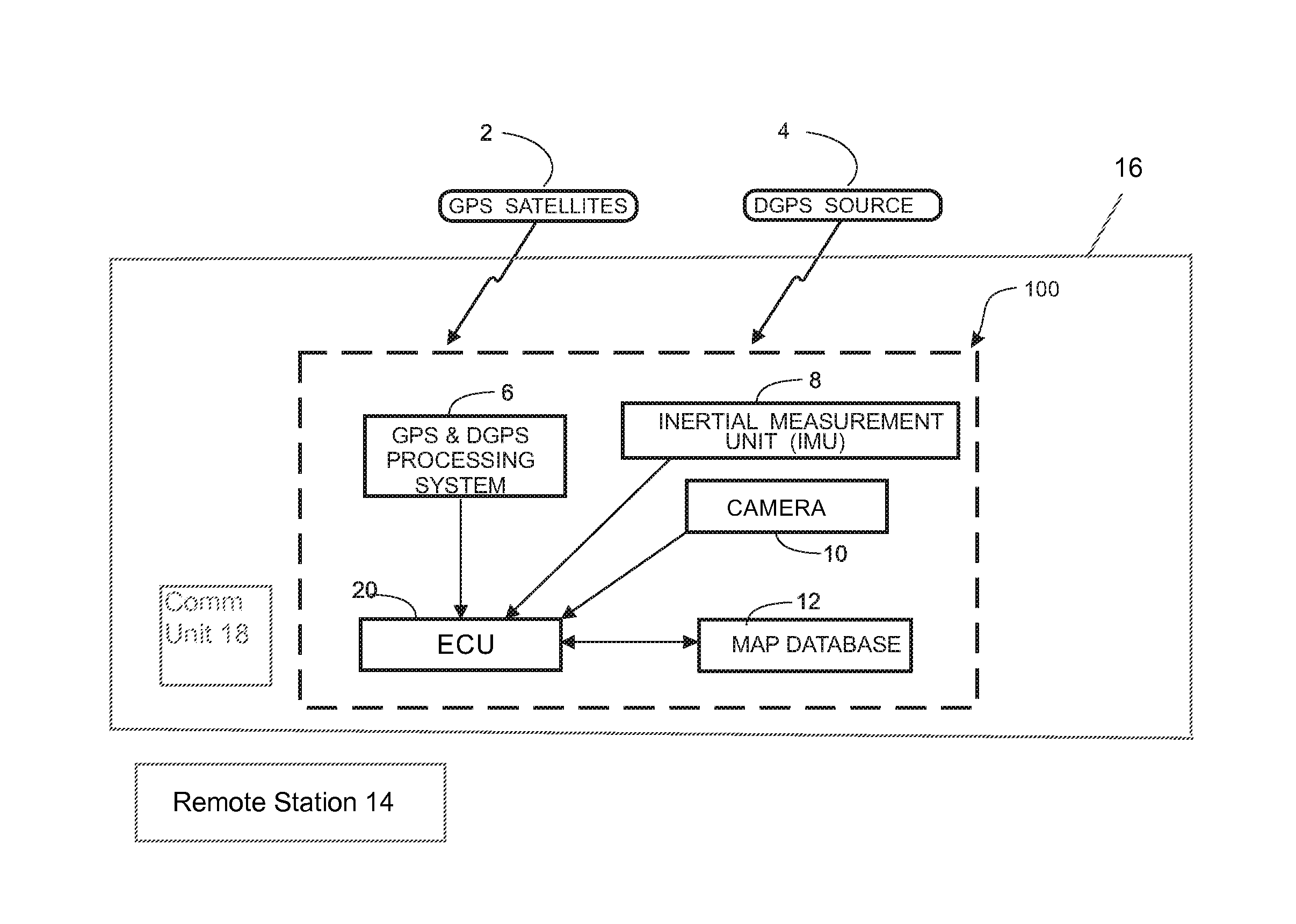
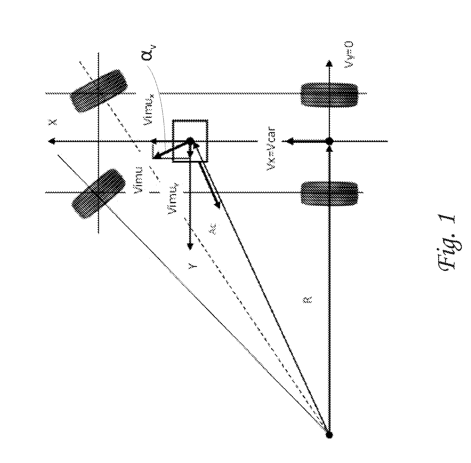
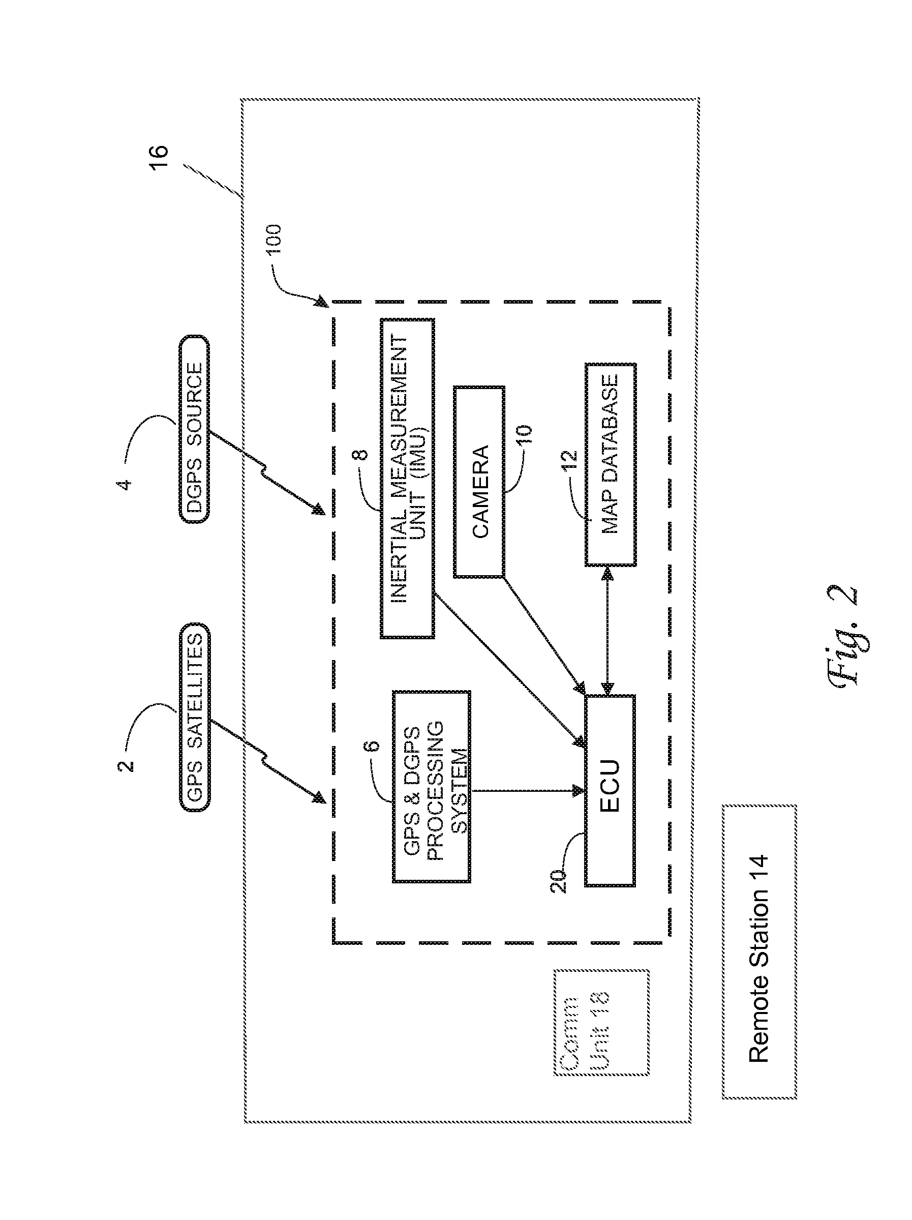
[0030]An object of the present invention is to provide a mapping system for probe vehicles. To do this, basic engineering solutions for a GPS-corrected IMU angular and displacement location system primarily for mass produced cars are presented. This objective is accomplished by:

[0031]1) Using a device containing a camera, a GPS or equivalent receiver, communication apparatus, IMU, and an ECU, comprising an electronic control system with the inertial measurement unit (IMU) mounted together at an appropriate location for imaging an area external to the vehicle.

[0032]2) Manufacturing IMUs in accordance with the mass-production MEMS technology at a cost of a few dollars per unit. An IMU can comprise 3 accelerometers and 3 gyroscopes or more generally, a plurality of accelerometers and / or a plurality of gyroscopes. Sometimes, it also comprises a 3 axis magnetometer.

[0033]3) Replacing the expensive, currently in-use self-calibration system for the correction of the changing errors in the ...


PUM


Abstract

Vehicle-mounted device includes an inertial measurement unit (IMU) having at least one accelerometer or gyroscope, a GPS receiver, a camera positioned to obtain unobstructed images of an area exterior of the vehicle and a control system coupled to these components. The control system re-calibrates each accelerometer or gyroscope using signals obtained by the GPS receiver, and derives information about objects in the images obtained by the camera and location of the objects based on data from the IMU and GPS receiver. A communication system communicates the information derived by the control system to a location separate and apart from the vehicle. The control system includes a processor that provides a location of the camera and a direction in which the camera is imaging based on data from the IMU corrected based on data from the GPS receiver, for use in creating the map database.

Description

CROSS REFERENCE TO RELATED APPLICATIONS[0001]This application is a continuation-in-part of U.S. patent application Ser. No. 14 / 069,760 filed Nov. 1, 2013, now U.S. Pat. No. 8,914,196.FIELD OF THE INVENTION[0002]The present invention relates generally to arrangements and methods for mapping terrain including roads using probe vehicles traveling on the roads, wherein each vehicle contains one or more cameras with GPS-corrected IMUs.BACKGROUND OF THE INVENTION[0003]A detailed discussion of background information is set forth in U.S. patent application Ser. Nos. 14 / 069,760 and 13 / 686,862 which is incorporated by reference herein.[0004]Electronic crash sensors used to sense crashes for airbag deployment currently in production comprise one or more MEMS accelerometers that measure acceleration at the sensor location. These accelerometers are typically produced by micromachining a single crystal of silicon and the sensing elements are frequently in the form of a beam or tuning fork. The si...

Claims


Application Information

Patent Timeline
IPC IPC(8): G01C21/16B60W30/00G06T7/00G01S19/13
CPCG01C21/165G01S19/13B60W30/00G06T2207/30252G06T2207/10004G06T2207/30244G06T7/0042B60R21/0132G06T7/73G01C21/1652G01C21/1656
Inventor BREED, DAVID S.BREED, RYAN
Owner INTELLIGENT TECH INT
Why Eureka
Try Eureka