Capacitance touch slider

a capacitance slider and touch technology, applied in the direction of static indicating devices, speed measurement using gyroscopic effects, instruments, etc., can solve the problems of not always optimal for controlling scrolling, and not always optimal for mouse us

Inactive Publication Date: 2005-03-24
MICROSOFT TECH LICENSING LLC
View PDF62 Cites 116 Cited by
  • Summary
  • Abstract
  • Description
  • Claims
  • Application Information

AI Technical Summary

Benefits of technology

[0007] An aspect of the present invention is directed to a device for detecting the position of a pointing member such as a human finger or other object on a touch-sensitive scrolling pad. The device may include a frequency ratio determinator, such as in the form of an electronic circuit, coupled to an arrangement of capacitive nodes such as conductive plates and / or conductive traces of a printed circuit board. The frequency ratio determinator may include dual independent oscillators used to generate pulses at frequencies dependent upon the capacitance of the conductors resulting from the position of the finger on the conductors. The frequency ratio determinator may count the pulses from each oscillator over a time interval and / or determine the finger position from the ratio of the number of pulses counted from each oscillator. Measuring the ratio (i.e., a “ratio-metric” design) of the pulse counts results in the rejection of common-mode errors and drift that may be caused by, e.g., ambient temperature fluctuations, damage to the surface of the scrolling pad (caused, for example, by hand lotion or spilled beverages), finger size, and manufacturing tolerances.
[0009] According to yet another aspect of the present invention, the conductors, which sense the finger or other object, may be of various shapes, preferably wedge-shaped such as triangular, and disposed in the touch pad of the device such that the finger covers both traces simultaneously when used properly. Moreover, more than two conductors may be used, such as by using multiple interdigitated conductors, to eliminate errors caused by the finger moving in a direction transverse to the intended axis of motion along the scrolling pad. By interdigitating the traces, potential errors caused when a finger is rolled in a direction transverse from movable axis can be minimized.
[0010] According to still another aspect of the present invention, the measuring portion may include a counting mechanism for counting the number of pulses generated by the oscillators. The counting mechanism may include a high frequency counter so that the pulses may be read quickly. This is helpful in reducing the effects of the environmental 60 Hz hum generated by the alternating current power source.

Problems solved by technology

However, the mouse is not always an optimal device for controlling scrolling.
Although some mice have scroll wheels, these wheels are also not ideal for some users, as they require substantial manual dexterity to be able to control the mouse, mouse wheel, and mouse buttons simultaneously.
Another reason a mouse is not necessarily optimal for scrolling is that it requires a user who is typing on a keyboard to remove one of his or her hands from the keyboard to the mouse, and then back to the keyboard to continue typing.
However, the two-dimensional touch pad is not always convenient because of the tendency to not be able to place the finger accurately on the edge of the touch pad.
Further, inaccurate touching of the touch pad will move the cursor instead of scrolling, causing frustration to the user.

Method used


Image

  • Capacitance touch slider
  • Capacitance touch slider
  • Capacitance touch slider

Examples


Embodiment Construction

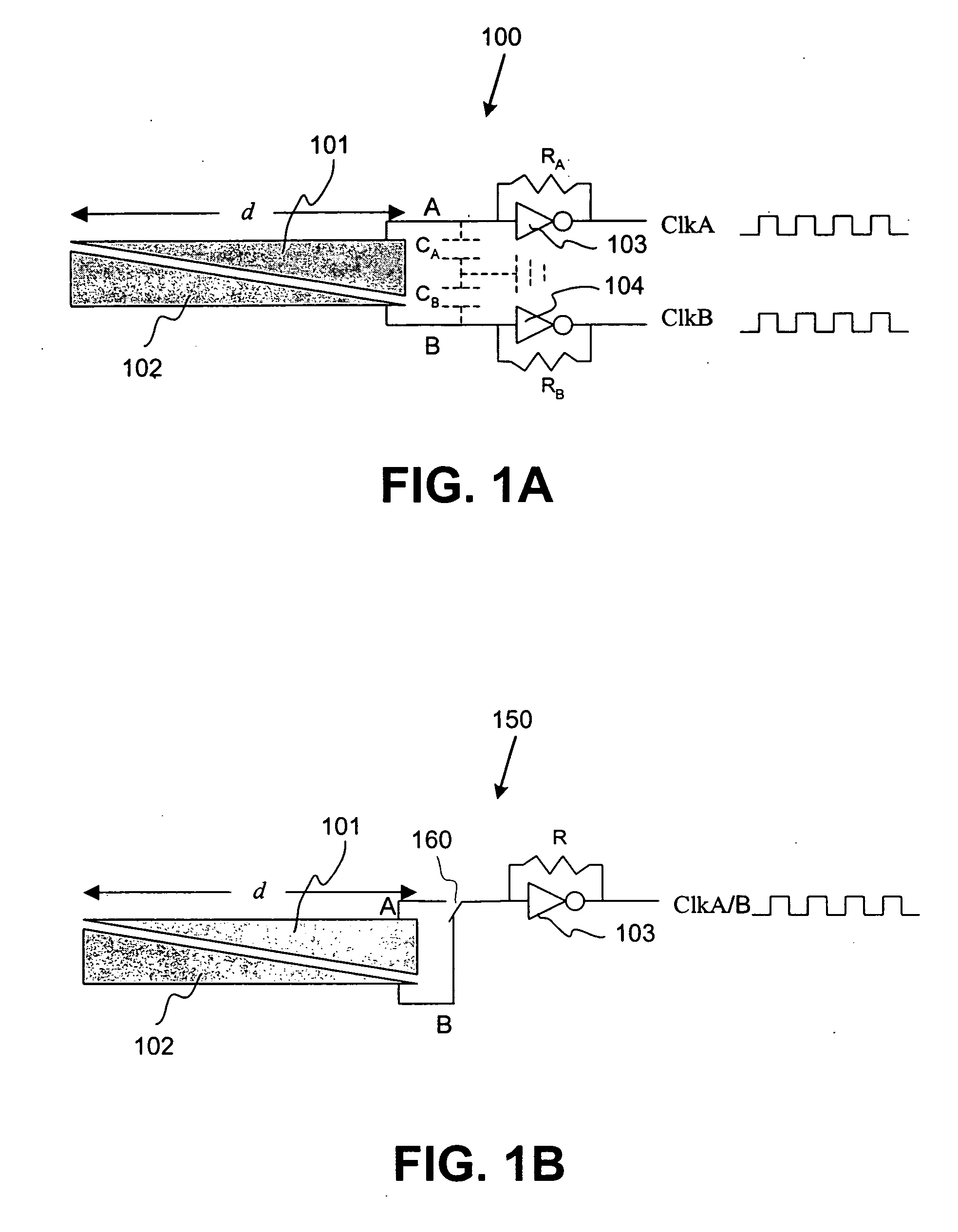
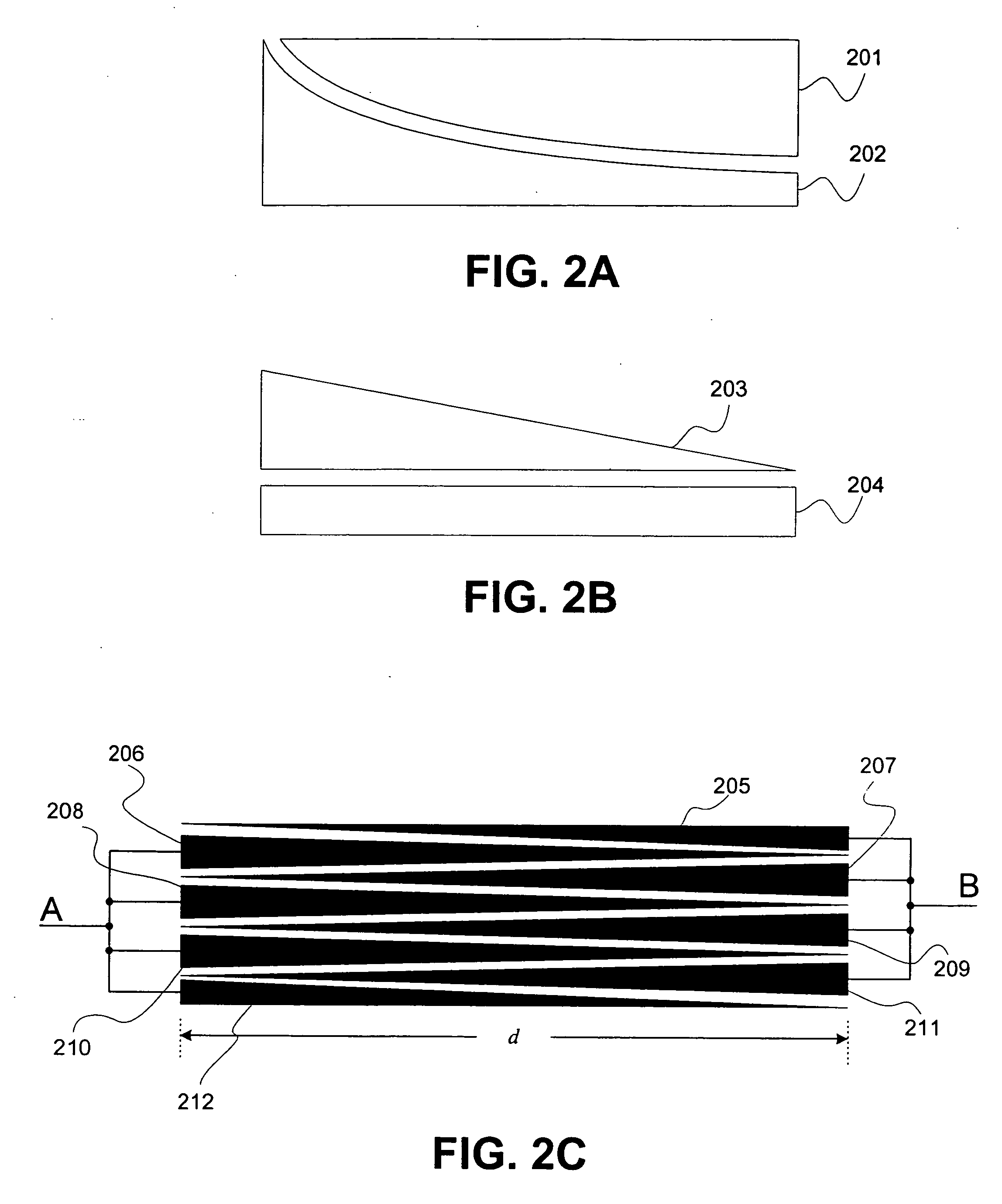
[0020] Referring to FIG. 1A, an exemplary embodiment of a capacitance touch slider 100 has two capacitive nodes such as conductive plates 101, 102. The conductive plates 101, 102 function to sense the position of, e.g., a human finger, along an axial direction d. As will be discussed below, the conductive plates 101, 102 may be variously shaped, although in the present example each of the conductive plates 101, 102 is triangular in shape.

[0021] To allow the position of the finger to be sensed, each conductive plate 101, 102 may be a capacitive part of a respective different oscillator. In the present embodiment, a first digital resistor-capacitor (RC) oscillator (hereafter called “oscillator A” in this embodiment) includes conductive plate 101 (which provides capacitance), a resistance RA such as from a simple resistor, and an inverter103 preferably of the Schmitt type. Also, a second digital RC oscillator (hereafter called “oscillator B” in this embodiment) includes conductive pla...


PUM


Abstract

A device for detecting the position of a human finger or other object on a touch-sensitive scrolling pad. Dual independent oscillators may be used to generate two pulse trains at frequencies dependent upon the capacitance of two conductors resulting from the position of the finger on the conductors. The pulses from each oscillator may be counted over a time interval. A ratio-metric measurement may be taken by calculating the ratio of the two counts, and a sum may also be calculated. The ratio of the two counts relates to finger position on the device, and their sum relates to finger pressure upon the device.

Description

RELATED APPLICATIONS[0001] This application is a continuation of U.S. patent application Ser. No. 09 / 820,747, entitled “Capacitance Touch Slider,” filed Mar. 30, 2001.FIELD OF THE INVENTION [0002] The present invention is directed generally to touch-sensitive pads and associated devices, and more particularly to capacitance touch sliders and methods for detection of the position of a pointing member thereon. BACKGROUND OF THE INVENTION [0003] Personal computers and other similar devices have a multitude of possibilities for providing user input. For instance, most computers today are used in conjunction with a mouse or similar pointing device for controlling the position of a cursor on a display. The mouse is also often used for scrolling in, e.g., word processing applications or other similar applications. [0004] However, the mouse is not always an optimal device for controlling scrolling. Although some mice have scroll wheels, these wheels are also not ideal for some users, as the...

Claims


Application Information

Patent Timeline
Patent Type & Authority Applications(United States)
IPC IPC(8): G06F3/033G06F3/044
CPCG06F3/03547G06F2203/0339G06F3/044G06F3/0362G06F3/0445
Inventor SINCLAIR, MICHAEL J.HINCKLEY, KENNETH P.KAJIYA, JAMES T.SHERMAN, NATHAN C.
Owner MICROSOFT TECH LICENSING LLC
Why Eureka
Try Eureka