Pneumatically actuated valve for internal combustion engines

a technology of pneumatic actuator and internal combustion engine, which is applied in the field of pneumatic actuator of internal combustion engine, can solve the problems of affecting engine performance, creating a great deal of friction, and relatively expensive system operation

Inactive Publication Date: 2006-11-28
KLEIN JEFFREY F +1
View PDF2 Cites 30 Cited by
  • Summary
  • Abstract
  • Description
  • Claims
  • Application Information

AI Technical Summary

Problems solved by technology

Valves which rely on a cam shaft usually require heavy springs and a large number of other moving parts that absorb a large amount of energy and create a great deal of friction.
Additionally, such systems are relatively expensive to operate.
Unfortunately, a problem with this intake valve assembly is that inertia and, to a lesser extent friction, retards the valve's speedy closure, thus negatively affecting engine performance.
While this variable spring force intake valve system is reliable, it still presents a lingering concern.
Thus, an insufficient amount of intake air enters the cylinders, negatively effecting engine performance.
While the valve assembly disclosed in this provisional patent application is sound, there is a slight disadvantage associated with this air distribution system.
Namely, the air distribution system, as disclosed, requires lubrication for the rotating disks and upon heating the presently available lubrications may release unwanted and harmful hydrocarbons into the atmosphere.

Method used


Image

  • Pneumatically actuated valve for internal combustion engines
  • Pneumatically actuated valve for internal combustion engines
  • Pneumatically actuated valve for internal combustion engines

Examples


Embodiment Construction

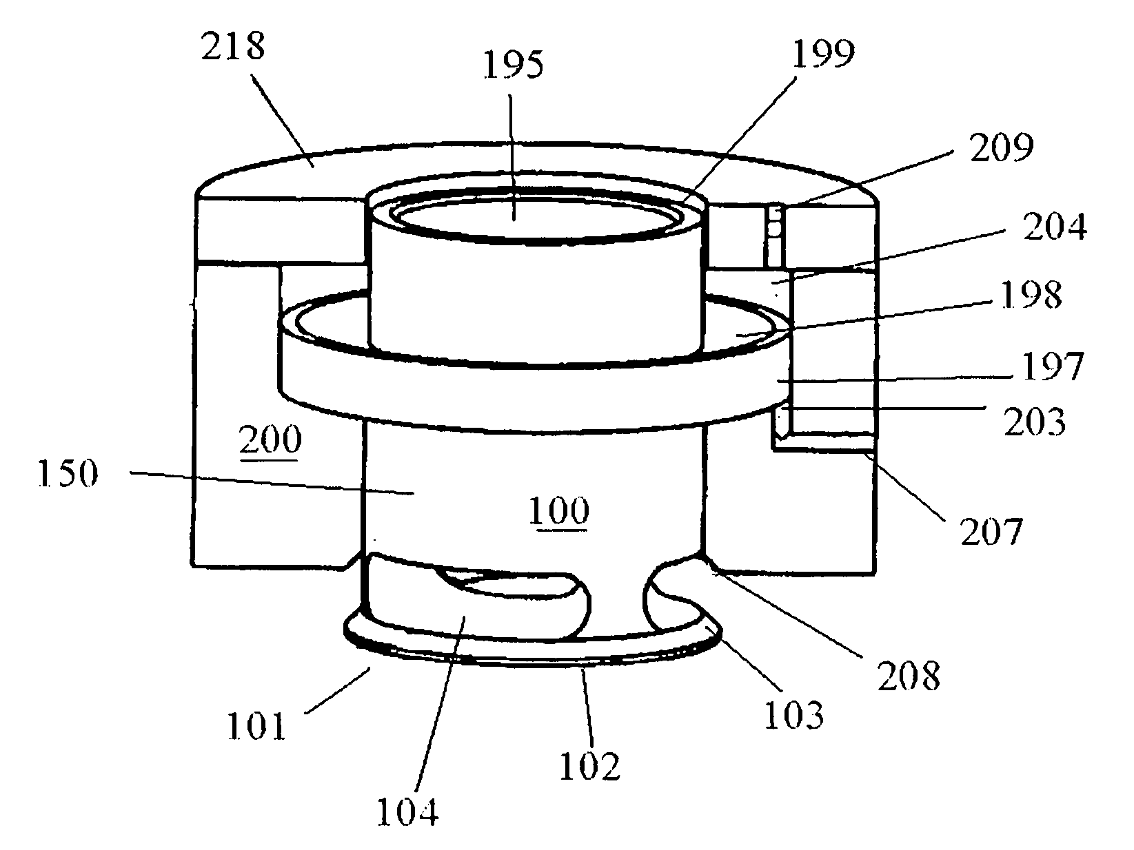
[0023]The present invention is a pneumatically actuated valve assembly for use as exhaust and / or intake valve on either two- or four-stroke internal combustion engines, inclusive of the pneumatically actuated valve itself, plus forced air distribution and timing mechanisms for controlling the valve. While the assembly is described herein as being pneumatically actuated by means of forced or compressed air, one skilled in the art will recognize that other pressurized gases may be suitable for actuating the valve of the present invention.

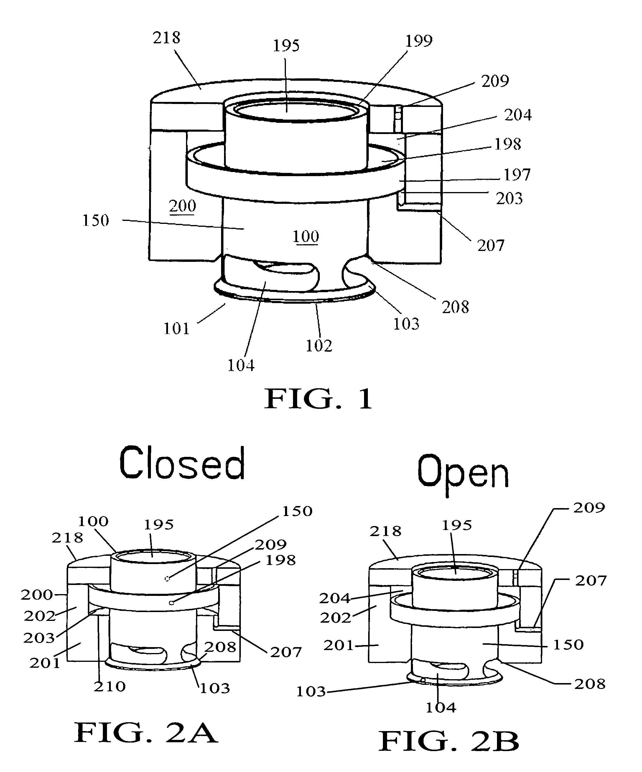
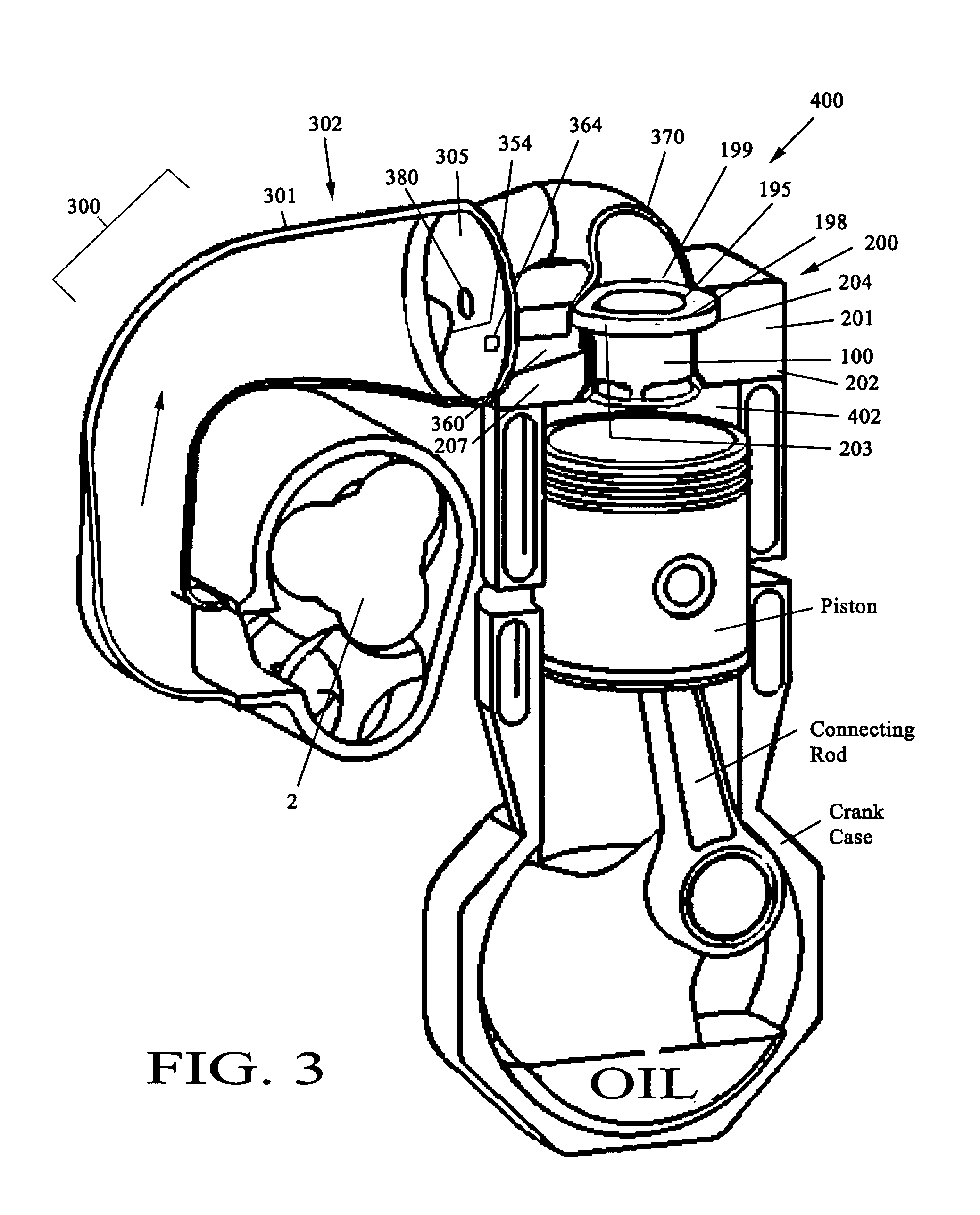
[0024]FIG. 1 depicts the structural features of an exemplary pneumatically actuated valve 100 for use with internal combustion engines according to the present invention. The pneumatically actuated valve assembly generally includes a valve 100, a valve housing 200 and an air distribution and timing mechanism 300 (to be described with reference to FIG. 3). The various components are described in more detail as follows.

Valve 100 and Valve Housing 200

[00...


PUM


Abstract

A pneumatically actuated valve assembly for use as intake and / or exhaust valves on two- or four-stroke internal combustion engines. The assembly includes a valve (100), valve housing (200), and compressed gas distribution and timing mechanisms (FIGS. 5–8). The valve (100) is comprised of a short light weight hollow cylindrical body with a capped lower end and an opened upper end. The valve is further defined by a plurality of ports (104) adjacent to the lower end and a collar (198) encircling the body adjacent the upper end. The valve housing (200) is hollow and tubular having a larger diameter upper section and a smaller diameter lower section in which the valve (100) slides up to close and down to open. The housing (200) further includes hollow channels which direct compressed gas, managed by the distribution and timing mechanism, alternately towards the areas above and below the valve collar at regular intervals to open and close the valve, respectively.

Description

CROSS-REFERENCE TO RELATED APPLICATIONS[0001]The present application is related to U.S. Pat. No. 6,349,691 issued on Feb. 26, 2002 for an “Automatic, Pressure Responsive Air Intake Valve for Internal Combustion Engine”. It is further related to U.S. Provisional Patent Application No. 60 / 444,532 for an Energy Efficient Intake Valve Assembly filed on Jan. 31, 2003.TECHNICAL FIELD[0002]The present invention relates to a valve and, more particularly, to a pneumatically actuated valve for use as an intake and / or exhaust valve on either a two- or four-stroke internal combustion engine.BACKGROUND ART[0003]Generally, four stroke internal combustion engines utilized valves to allow exhaust to leave the working (combustion) chamber of the engine cylinder after the combustion stroke, as well as to allow a new air charge to enter the cylinder to begin the cycle anew during the intake stroke. Two stroke internal combustion engines on the other hand may utilize valves for both intake and exhaust ...

Claims


Application Information

Patent Timeline
Patent Type & Authority Patents(United States)
IPC IPC(8): F01L9/02F01L7/02F01L7/06F01L7/10F01L7/12F01L9/16F02B33/38F02B33/44
CPCF01L1/28F01L3/20F01L5/04F01L7/02F01L7/06F01L7/10F01L7/12F01L9/026F02B33/38F02B33/44F02B29/0406F01L9/16
Inventor KLEIN, JEFFREY F.MIKHAILOV, KONSTANTIN
Owner KLEIN JEFFREY F
Why Eureka
Try Eureka