Rolling press member for power switch

Inactive Publication Date: 2005-05-24
ATOM TECHNOLOGIES
View PDF5 Cites 5 Cited by
  • Summary
  • Abstract
  • Description
  • Claims
  • Application Information

AI Technical Summary

Benefits of technology

[0007]The object of the invention is to provide a rolling press member for power switch having an inlayed roller at an end portion of the press member. Using the roller, displacements of a contact plate an interior of a switch housing are made smoother. The invention is characterized that, a metal roller capa

Problems solved by technology

The elevated temperatures melt and drain away the grease I accumulated between the lower end of the center column B1 and the outer surfaces of the press member

Method used


Image

  • Rolling press member for power switch
  • Rolling press member for power switch
  • Rolling press member for power switch

Examples


Embodiment Construction

[0017]To better understand the invention, detailed descriptions shall be given with the accompanying drawings below.

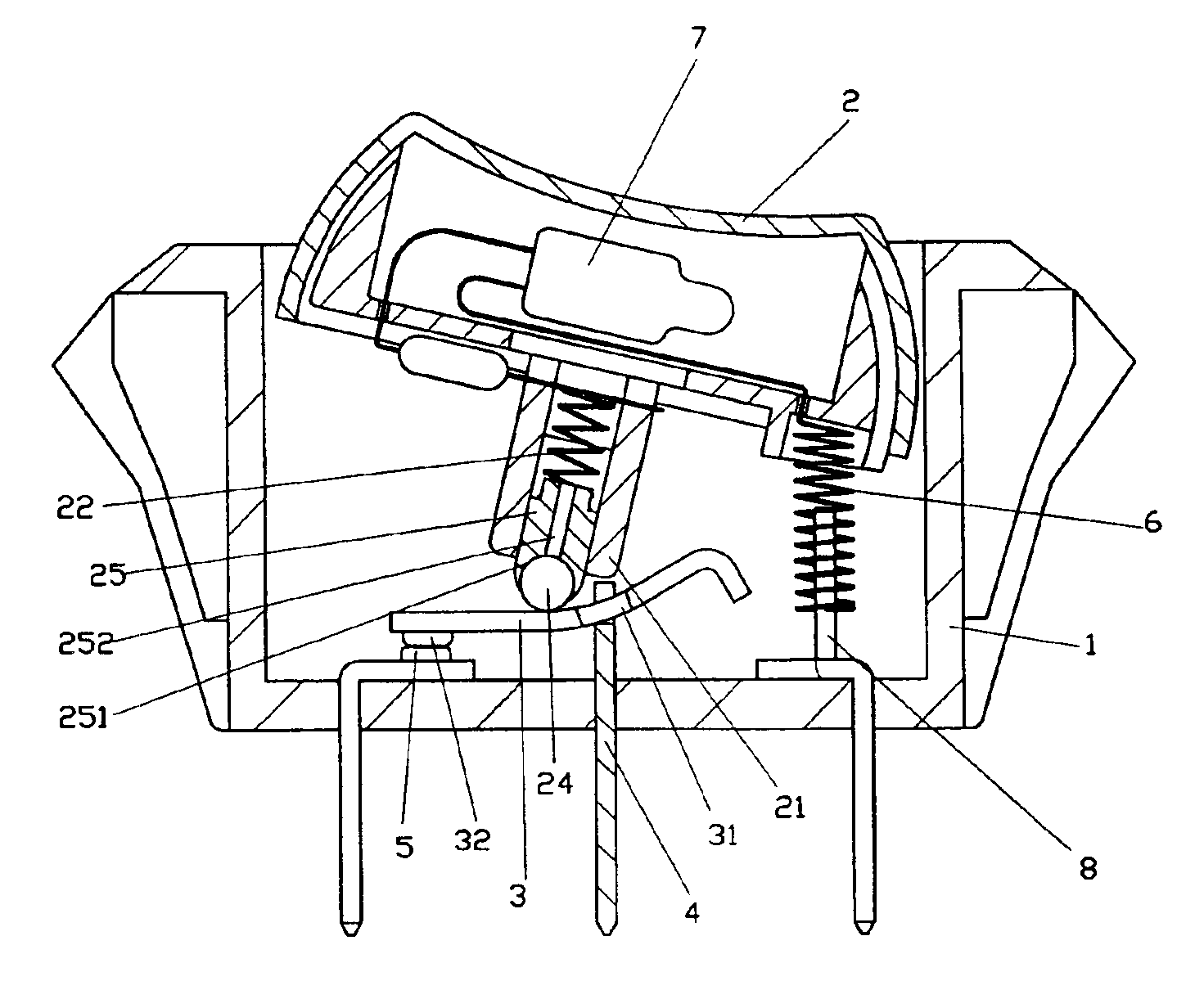
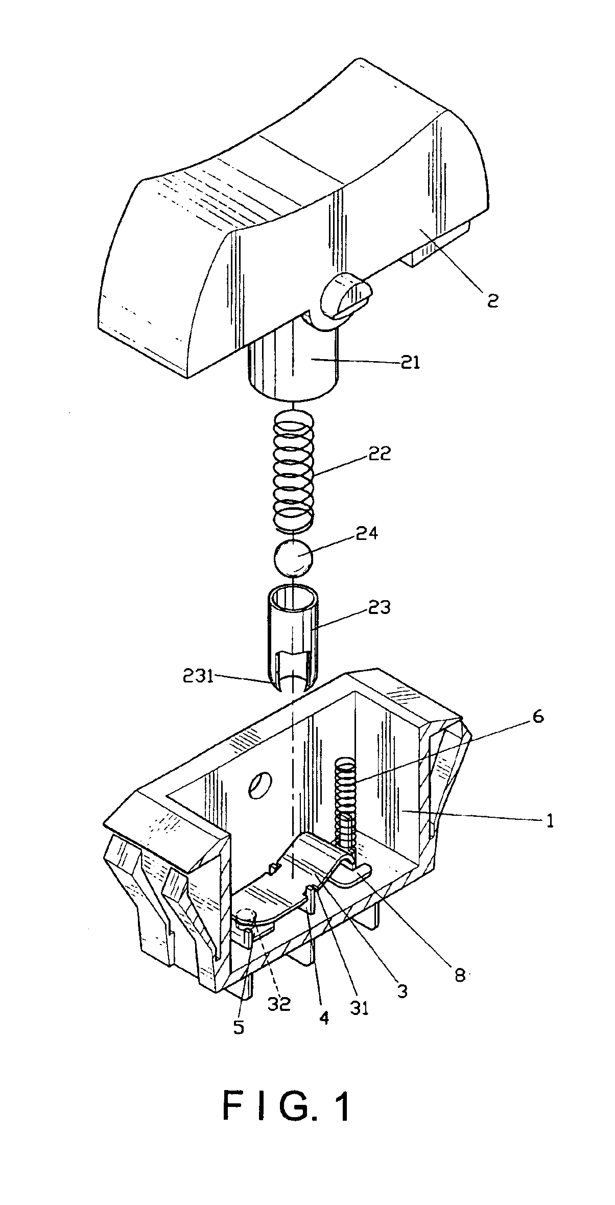
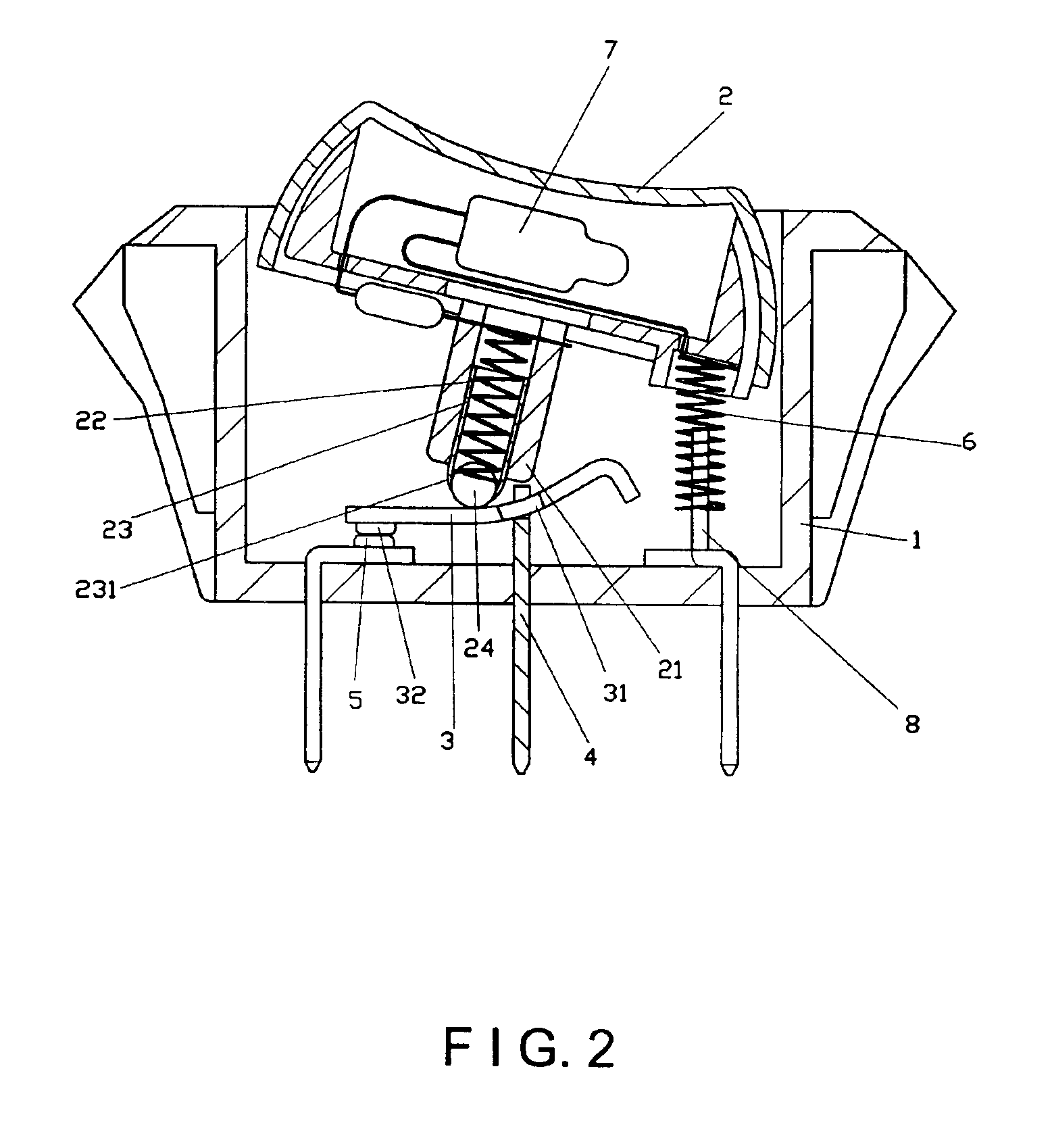
[0018]Referring to FIGS. 1 and 2, a fundamental structure of a switch in a first embodiment according to the invention comprises:

[0019]a switch housing 1;

[0020]a button 2 pivotally disposed at the switch housing 1; and having a center column 21 formed at a bottom center thereof, and an elastic member 22 disposed at an interior thereof and for pressing against a press member 23 for forming an elastically contractible end;

[0021]an arched contact plate 3 being in contact at a bottom portion; and

[0022]having symmetrical apertures 31 at edges of a middle section thereof that are connected to a conducting strap 4, so as to erect the contact plate 3 at a bottom portion of the switch housing 1, and a contact point 32 at one end thereof, wherein the contact point 32 is in communication with another live wire conducting strap 5 when moving in a downward direction; and

[0023]an el...


PUM


Abstract

A rolling press member for power switch includes a metal roller capable of free rolling movements and disposed at an end portion of the press member, with the roller pressing against an internal contact plate. When turning on and off the switch, the roller displaces at the contact plate using rolling movements thereof, thereby enabling smoother operations of the power switch.

Description

BACKGROUND OF THE INVENTION[0001](a) Field of the Invention[0002]The invention relates to a rolling press member for power switch, and more particularly, to a rolling press member having a roller at an end portion of the press member placed in a center column of a button, thereby elevating displacement smoothness of a contact plate at an interior of a switch housing.[0003](b) Description of the Prior Art[0004]Switches are generally provided for various kinds of electric appliances or mechanical apparatus as controlling means for shutting down or conducting power supplies. To be more precise, these switches are utilized for facilitating turning on or off power supplies of these equipments. Referring to FIG. 7 showing a conventional fundamental structure of a common switch, a switch housing A is pivotally disposed with a button B at an upper portion thereof. The button B has a center column B1 at a bottom center thereof. An interior of the center column B1 is provided with an elastic ...

Claims


Application Information

Patent Timeline
IPC IPC(8): H01H23/00H01H23/20H01H23/02H01H23/24H01H23/16
CPCH01H23/205
Inventor HUANG, CHYONG-YEN
Owner ATOM TECHNOLOGIES
Why Eureka
Try Eureka