Non-separating diffuser for holes produced by a two step process

a two-step process and diffuser technology, applied in the direction of manufacturing tools, machines/engines, cleaning using liquids, etc., can solve the problems of high cost and difficulty of fabrication, super-cooled airfoils are very difficult to manufacture, and the effect of cos

Inactive Publication Date: 2005-05-24
RTX CORP
View PDF6 Cites 18 Cited by
  • Summary
  • Abstract
  • Description
  • Claims
  • Application Information

AI Technical Summary

Benefits of technology

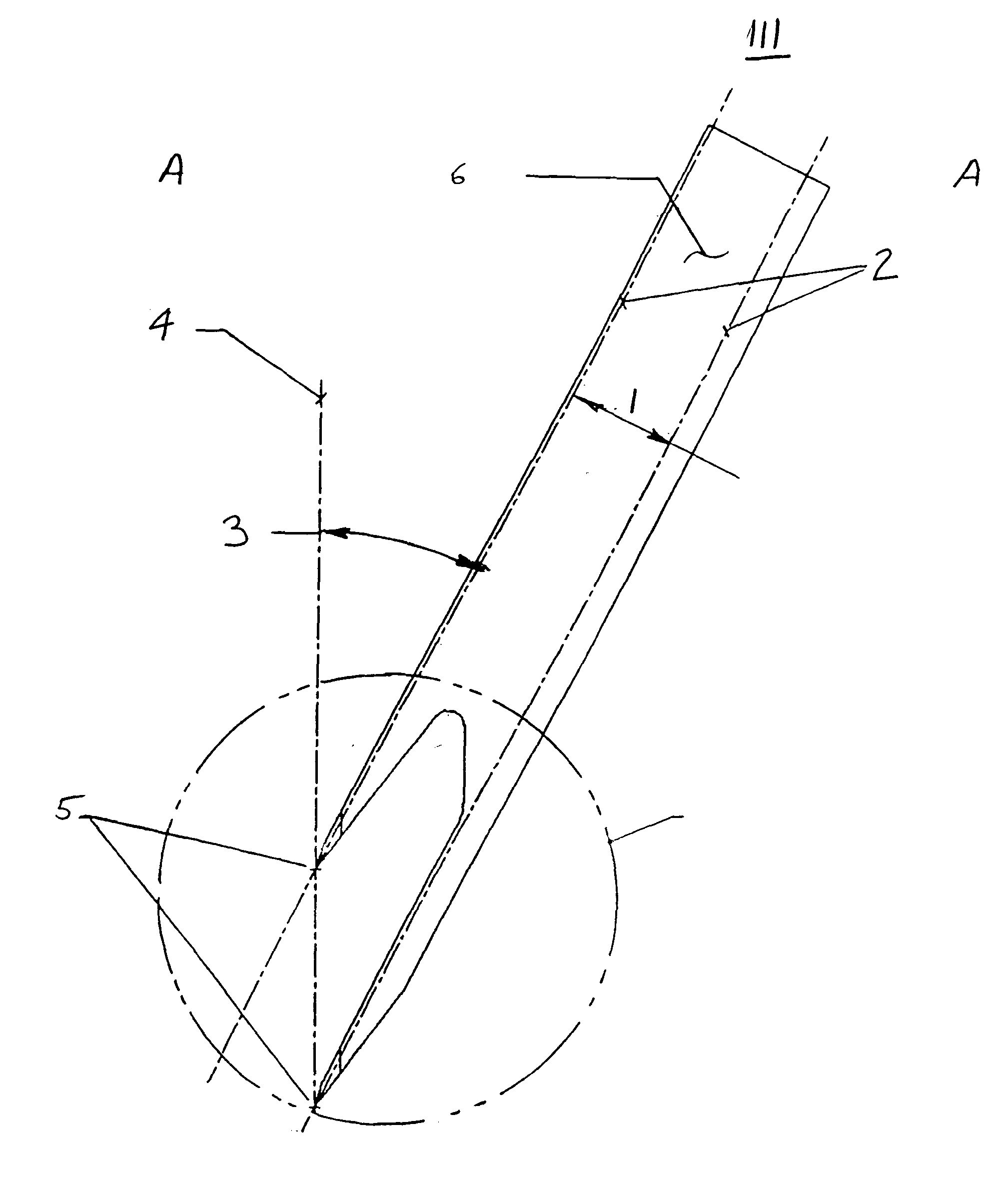
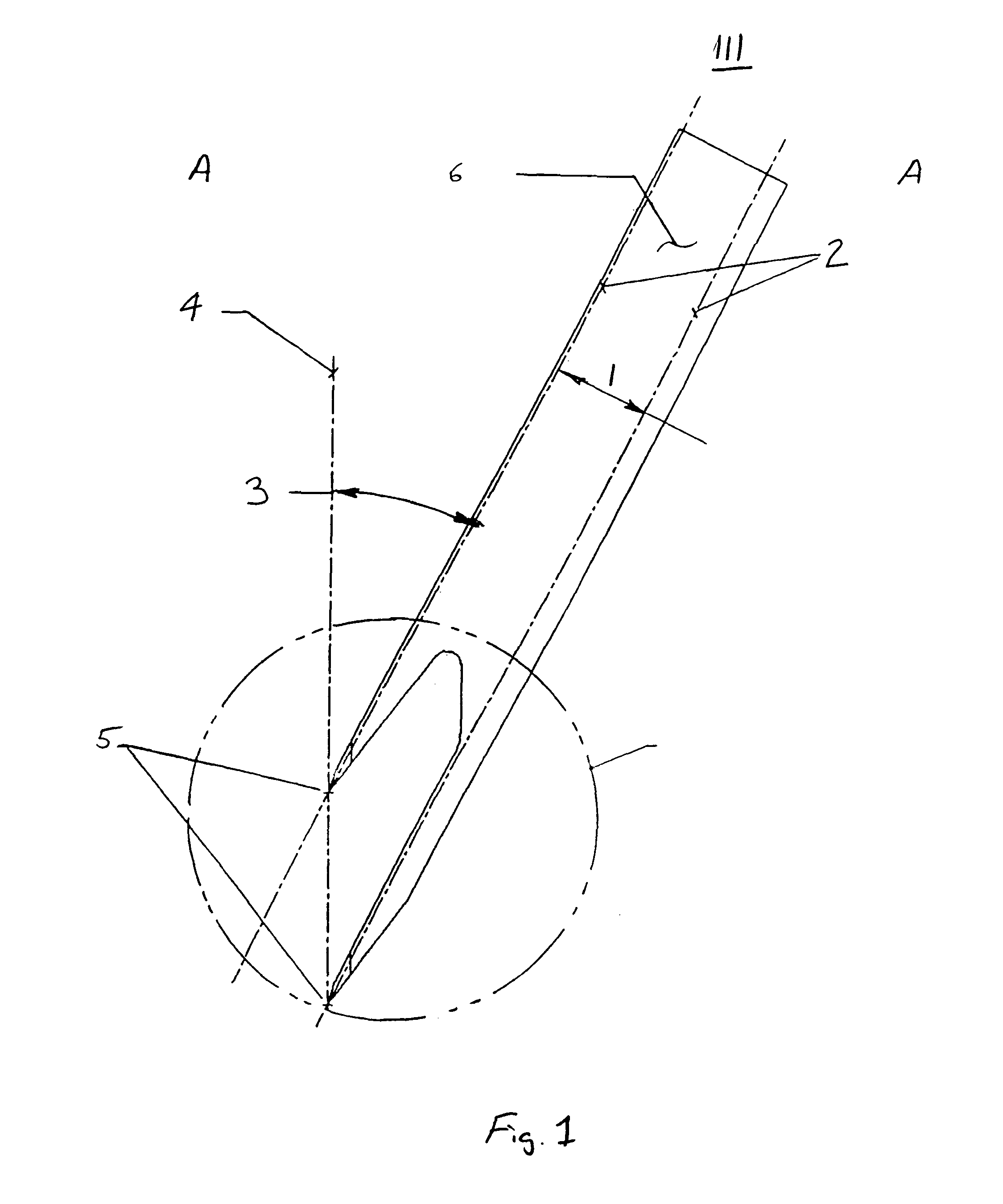
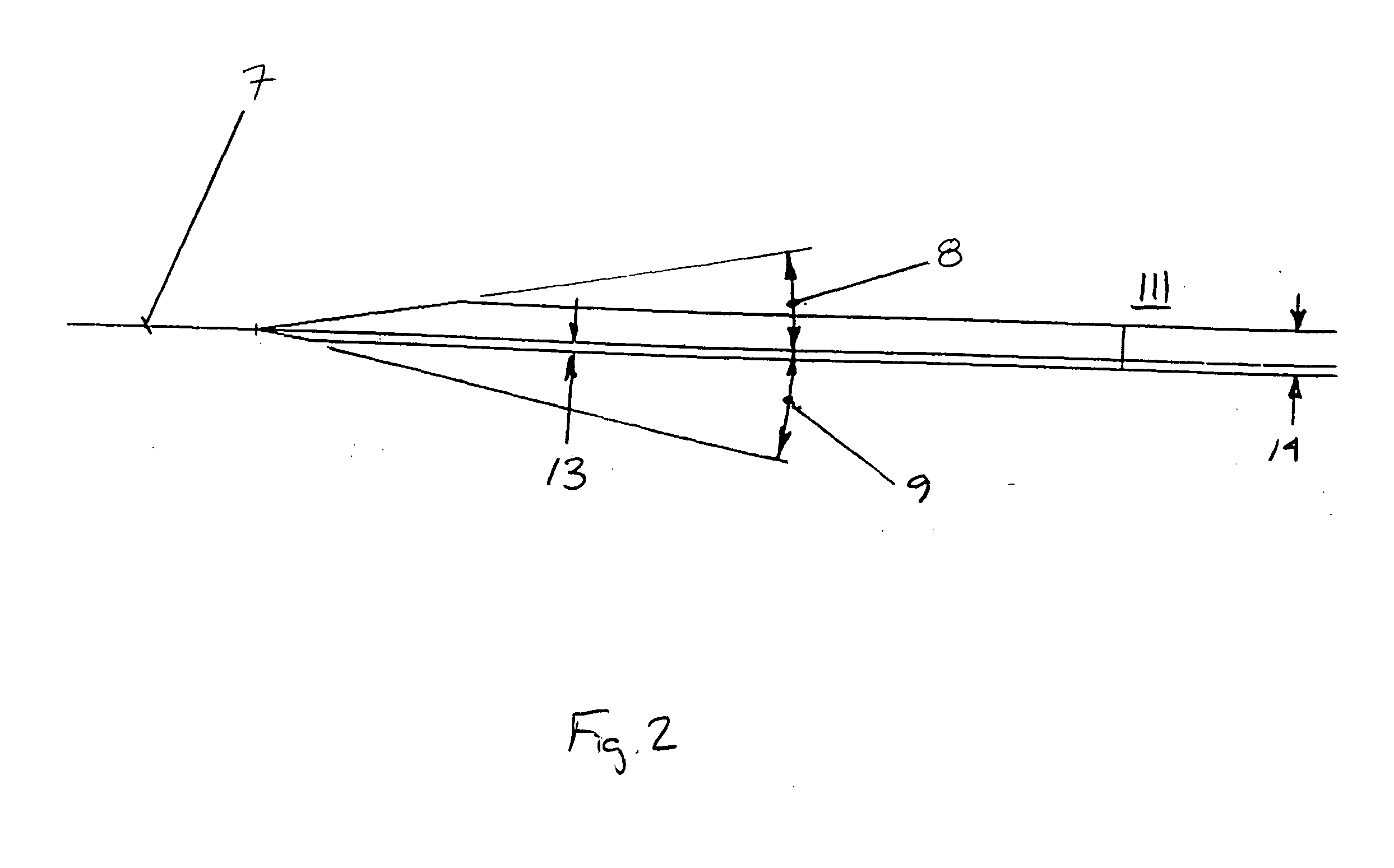
[0014]It is a further object of the present invention to provide a method for forming non-separating diffusers in a part which comprises the steps of fabricating at least one metering hole in a part, and fabricating at least one diffuser by a different process or operation. The diffuser has an array of angled surfaces passing through a common nose point along the tooth centerline to provide a transition region from the through hole, to the diffuser portion of the hole. Where diffusion is desired, these surfaces continue beyond the part surface (under worst tolerance conditions). On surfaces where diffusion is not desired, these surfaces are truncated at a distance from the nominal centerline of the tooth so as to merely eliminate the step which would exist between the edge of the hole and the edge of the diffuser hole due to tolerances between the two operations.

Problems solved by technology

This is not a problem when both features are produced from a single electrode, but is a major problem if the hole is produced by one process and the diffuser is produced by a different process and / or operation.
There are several reasons to want to use one process to produce the metering hole and another process or operation to produce the diffuser, specifically, cost and difficulty of fabrication.
With regards to difficulty, drilling a “Vehr type hole” into a small cavity in modern “super-cooled airfoils” is very difficult with a single shaped electrode and is very costly if not impossible without back-striking the inner wall which causes a stress concentration factor in the already highly stressed inner wall.

Method used


Image

  • Non-separating diffuser for holes produced by a two step process
  • Non-separating diffuser for holes produced by a two step process
  • Non-separating diffuser for holes produced by a two step process

Examples


Embodiment Construction

)

[0019]The present invention teaches the creation of a preferably EDM'd diffuser whose centerline is nominally co-linear with the hole drilled through the wall which forms the meter section of the finished “Vehr” hole. The hole may be round or rectangular with filleted corners.

[0020]The present invention is herein described in terms of the EDM tool used to form the diffuser. While described as though the hole is drilled first, the process may in practice be reversed. The present invention is described herein with respect to a “comb electrode” having at least two teeth. However, it would be obvious to one skilled in the art to extend the teachings of the present invention to include the use of a single tooth electrode used to EDM one diffuser at a time, or, if “n” parallel holes exist in a plane, a comb of “n” teeth could be used to form the diffuser on “n” holes at a time. Therefore, as used herein, “comb electrode” refers as well to an electrode having only one tooth. In the case o...


PUM

PropertyMeasurementUnit
angleaaaaaaaaaa
angleaaaaaaaaaa
diffuser anglesaaaaaaaaaa

Abstract

A method for forming non-separating diffusers in a part includes fabricating at least one metering hole in a part, and fabricating at least one diffuser hole with an electrode comb in the part such that the diffuser hole intersects the metering hole at a transition region. The electrode comb includes a tooth including a nose comprised of a plurality of diffuser surfaces intersecting at a point on a tooth centerline. Each diffuser surface has a diffuser angle, and at least one of the diffuser surfaces is truncated by an offset from the tooth centerline.

Description

U.S. GOVERNMENT RIGHTS[0001]The invention was made with U.S. Government support under contract F33657-90-C-2212 awarded by the Department of the Air Force, and under contract N00019-97-C-0050 awarded by the Department of the Navy. The U.S. Government has certain rights in the invention.BACKGROUND OF THE INVENTION[0002](1) Field of the Invention[0003]The present invention relates to method to fabricate non-separating diffuser holes formed by way of a two step process and an electrode comb used in the method.[0004](2) Description of Related Art[0005]Cooling hole efficiency is of great consequence for High Pressure Turbine Blades in high performance aircraft gas turbine engines. To be achieve maximum efficiency, each hole ideally exhibits a small meter section to limit cooling air flow and a diffuser to slow down the air flow and spread it over the surface of the airfoil in a thin film.[0006]One common hole used to provide such cooling characteristics is the “Vehr” hole (disclosed in U...

Claims


Application Information

Patent Timeline
Patent Type & Authority Patents(United States)
IPC IPC(8): B23H9/10B23H9/00B23H1/04B23H9/14B23P15/02F01D5/18F02C7/00
CPCB23H9/10B61D15/00E21F5/06E21F5/20B08B15/002B08B3/022E01H8/105
Inventor KILDEA, ROBERT J.
Owner RTX CORP
Why Eureka
Try Eureka