Chair construction

a chair and back technology, applied in the field of furniture, can solve the problems of difficult to achieve all three of these goals, loosening or structural damage of the connector, and affixing the seat and back of the chair

Inactive Publication Date: 2005-05-31
MERCURIES ASIA
View PDF22 Cites 35 Cited by
  • Summary
  • Abstract
  • Description
  • Claims
  • Application Information

AI Technical Summary

Problems solved by technology

It is difficult to achieve all three of these goals.
Particular problems exist in affixing the chair seat and back to the frame.
Such connectors tend to become loose or structurally damaged through use.
Molded plastic often fails in the area of the connectors.
Another problem in conventional tubular chairs is providing suitable feet or the like at the bottoms of the legs.
It is difficult to connect the buttons or pads such that they are positioned flat on a supporting surface.
Another problem with conventional tubular chairs is providing a suitable arm rest.
These fasteners tend to become loose, thereby causing the arm rest to separate from the frame.

Method used


Image

  • Chair construction
  • Chair construction
  • Chair construction

Examples


Embodiment Construction

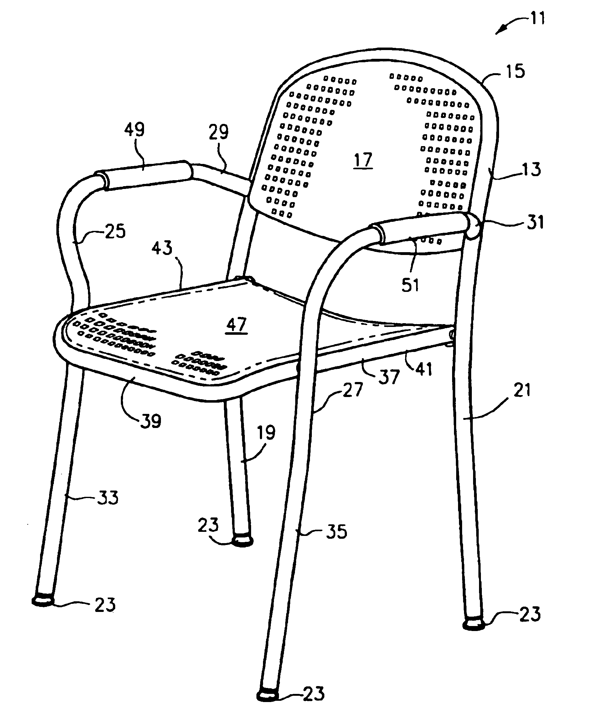
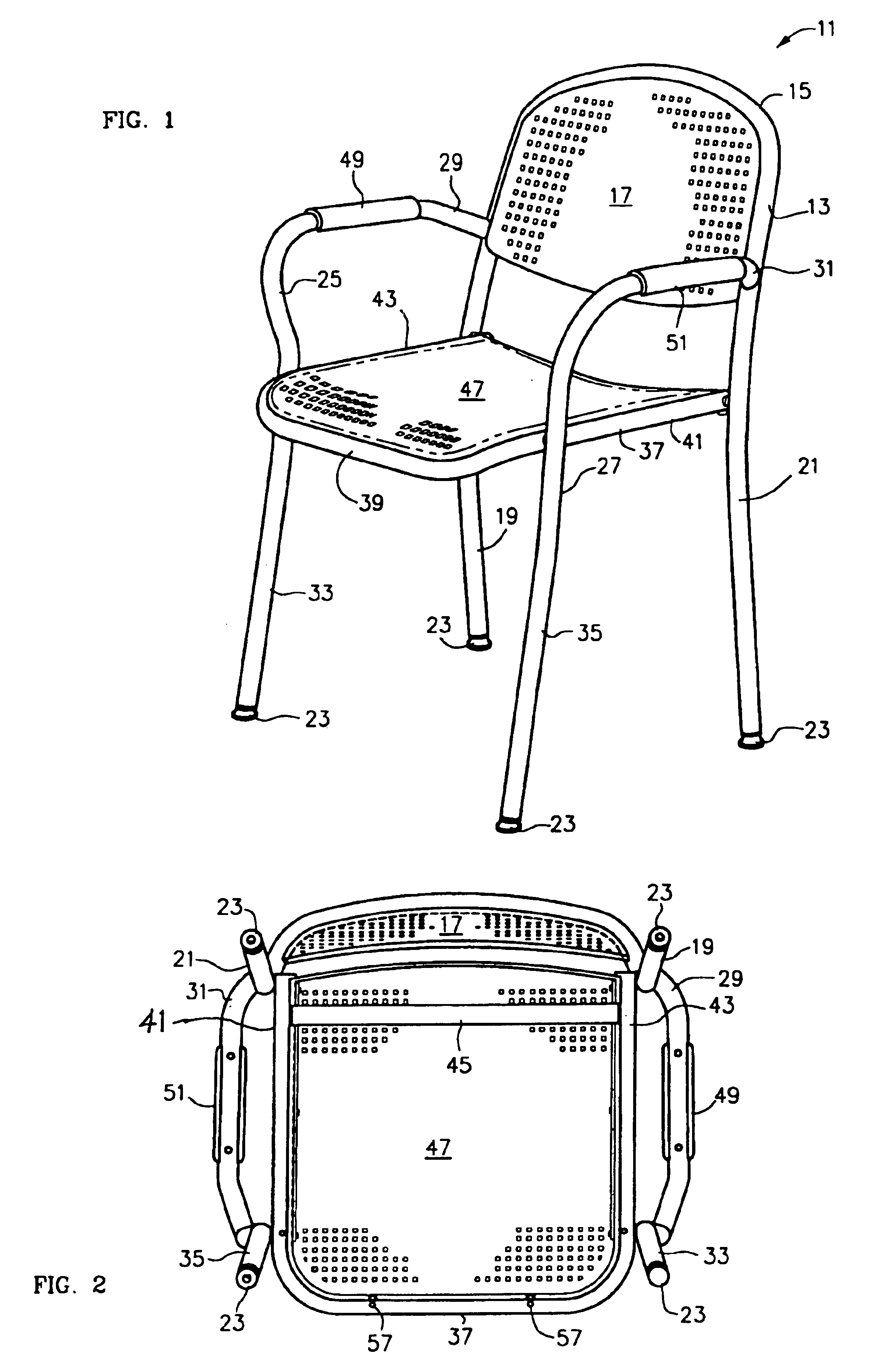
[0022]Referring now to the drawings, and first to FIG. 1, a chair according to the present invention as designated by the numeral 11. Chair 11 includes a tubular generally U-shaped back frame 13. Back frame 13 is made of tubular metal and it includes a seat back portion 15 that supports a seat back 17 and a pair of spaced-apart legs 19 and 21. Seat back 17 is preferably formed from molded plastic or the like. As will be described in detail hereinafter, feet 23 are provided at the ends of legs 19 and 21.

[0023]Chair 11 also includes a pair of spaced-apart tubular L-shaped side members 25 and 27. Side members 25 and 27 include generally horizontal arms 29 and 31, respectively. The ends of arms 29 and 31 are connected, preferably by welding, to back frame 13. As will be explained in detail hereinafter, arm members 29 and 31 have a affixed thereto armrests 49 and 51, respectively. Side members 25 and 27 also include leg members 33 and 35, respectively, having feet 23 at their bottom ends...


PUM


Abstract

A chair includes a tubular U-shaped back frame. The back frame defines a pair of spaced apart back legs. A pair of tubular L-shaped side members, each of which defines a front leg and an arm, are connected the back legs. A tubular U-shaped seat frame is connected to each of the front legs and each of the back legs. A connecting member is connected across the seat frame adjacent the connections of the seat frame to the back legs.

Description

FIELD OF THE INVENTION[0001]The present invention relates generally to the field of furniture, and more particularly to a tubular chair construction.BACKGROUND OF THE INVENTION[0002]Tubular chairs are generally well known. Tubular chairs typically include a tubular metal frame, which is welded together, and seat and back members affixed to the frame. Tubular chairs may be used in institutional or commercial settings, such as schools, offices, hotels, convention centers and the like. Tubular chairs may also be used in home settings as extra chairs or as outdoor furniture such as patio furniture and the like.[0003]Tubular chairs need to be relatively rugged, but relatively inexpensive and lightweight. It is difficult to achieve all three of these goals. Particular problems exist in affixing the chair seat and back to the frame. Generally, the seat and back portions are attached to the frame using screws, rivets, or the like. Such connectors tend to become loose or structurally damaged...

Claims


Application Information

Patent Timeline
Patent Type & Authority Patents(United States)
IPC IPC(8): A47C5/00A47C5/04
CPCA47C7/002A47C5/04
Inventor BALES, DAVID W.
Owner MERCURIES ASIA
Why Eureka
Try Eureka