Gas bleed system with improved control

a bleed system and gas technology, applied in the direction of safety/regulatory devices, servomotor components, servomotors, etc., can solve the problems of large step changes, difficulty in accurately controlling the release of gas from a higher pressure region to a lower pressure region, and inconsistent or varying flow passage sizes of conventional bleed valves, etc., to achieve cost-effective construction and efficient and durable use

Inactive Publication Date: 2005-06-07
LINCOLN INDUSTRIES CORP
View PDF19 Cites 0 Cited by
  • Summary
  • Abstract
  • Description
  • Claims
  • Application Information

AI Technical Summary

Benefits of technology

[0005]Among the several objects and features of the present invention may be noted the provision of a gas bleed system for releasing gas at a selectively adjustable flow rate; the provision of such a system which may be calibrated to obtain repeatable flow rates; the provision of such a system for use in a runaway control of an air motor for stopping the motor if it should start to run away; and the provision of such a system which is efficient and durable in use and cost-efficient to construct.

Problems solved by technology

It is difficult to accurately control a release of gas from a higher pressure region to a lower pressure region, particularly for an adjustable, low-level release.
Due to manufacturing tolerances, conventional bleed valves frequently exhibit inconsistent or varying sizes of flow passages.
Adjustments which are intended to produce minor incremental changes in flow rates can result in large step changes.
Consequently, the valves are over-sensitive, cannot be accurately calibrated, and are not repeatable in setting a selected rate of flow.
A problem of pump runaway is at times encountered, due for example to breakage of a discharge line or running out of the material being pumped.
That can damage the pump and cause expensive and time-consuming spills of material.
A drawback to runaway controls is that bleed valves are prone to be over-sensitive to adjustments, as described above.
It is difficult to accurately calibrate the bleed valve to obtain a desired cut-off speed or to repeat previously obtained settings.

Method used


Image

  • Gas bleed system with improved control
  • Gas bleed system with improved control
  • Gas bleed system with improved control

Examples


second embodiment

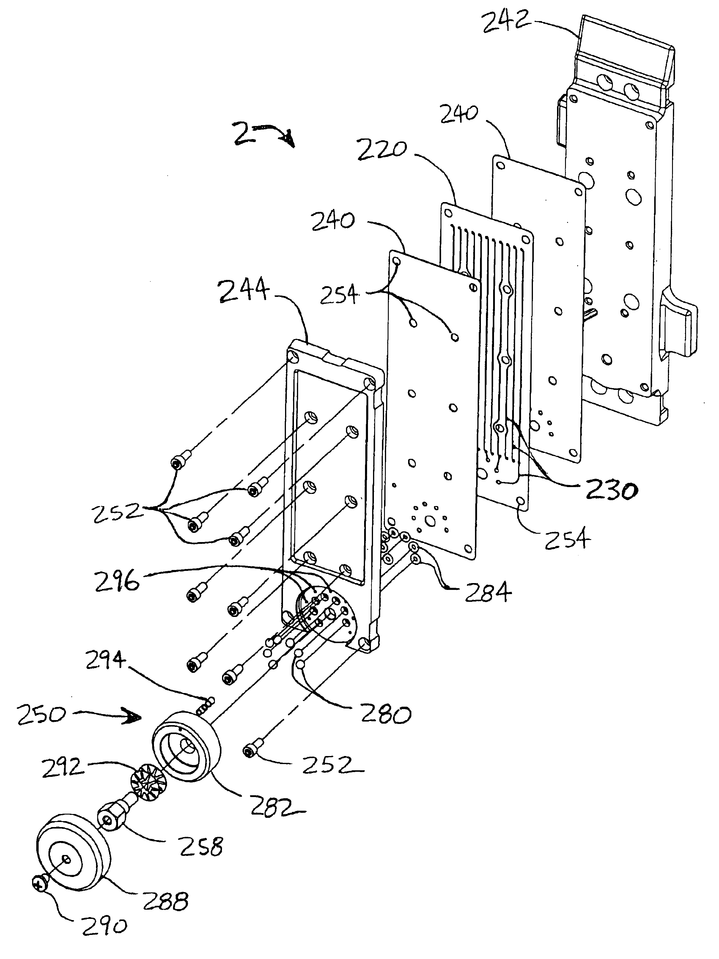
[0053]A second embodiment of the invention (FIGS. 5A and 5B) includes a plate 300 with channels 230 formed in both opposing faces 260, 262. The plate 300 has connecting holes indicated at 302 for passing air from a channel 230 on the front face 260 to a channel on the back face 262. The arrangement is such that turning the selector knob 282 to successive outlet holes 272 increments the distance traveled by the air by one, two or more down-and-back reaches 268 of grooving. This configuration increases the length of passageway on the plate compared to a plate 220 of the first embodiment having single face grooves, and is done so without increasing the size of the plate or density of grooves. For example, when the second outlet 272b is selected on the plate of FIG. 5A, air must travel two reaches 268 along the length of the plate, whereas only one reach is traversed on the plate of FIG. 4A. Thus, the plate 300 of FIG. 5A provides additional length and air resistance. Two gaskets 240 ar...


PUM


Abstract

A bleed system for venting pressurized gas at a selectively adjustable flow rate. The bleed system includes a plurality of bleed flow paths of different lengths providing varying resistance to the flow of air and a bleed path selector mechanism movable between a plurality of different settings corresponding with the different flow paths. The flow paths are defined by channels formed in a face of a plate and are connectable in series. The bleed system is applied in a runaway control for an air motor which shuts off the motor when its speed exceeds a predetermined cut-off speed. Selection of a different bleed flow path adjusts the cut-off speed.

Description

BACKGROUND OF THE INVENTION[0001]This invention relates to control of gas flows, and more particularly to a bleed system for releasing pressurized gas from a chamber at a selectively adjustable flow rate. The bleed system is described primarily herein for application in a runaway control for an air motor which shuts off the motor when its speed exceeds a predetermined threshold speed. However, it is understood that the bleed system may be applied in any device where pressurized gas is released at a controlled rate.[0002]It is difficult to accurately control a release of gas from a higher pressure region to a lower pressure region, particularly for an adjustable, low-level release. Due to manufacturing tolerances, conventional bleed valves frequently exhibit inconsistent or varying sizes of flow passages. Adjustments which are intended to produce minor incremental changes in flow rates can result in large step changes. Consequently, the valves are over-sensitive, cannot be accurately...

Claims


Application Information

Patent Timeline
Patent Type & Authority Patents(United States)
IPC IPC(8): F15B15/20F15B15/00F15B13/04F15B13/00
CPCF15B15/202F15B13/0406
Inventor HOLLAND, CHRISTOPHER D.
Owner LINCOLN INDUSTRIES CORP
Why Eureka
Try Eureka