Electrical actuator

a technology of actuators and actuators, applied in the direction of valve details, valve arrangement, operating means/releasing devices of valves, etc., can solve the problem of small installation spa

Active Publication Date: 2017-07-25
CAMERSON INT CORP
View PDF9 Cites 0 Cited by
  • Summary
  • Abstract
  • Description
  • Claims
  • Application Information

AI Technical Summary

Problems solved by technology

Therefore, often a “fail as is” device is necessary, which holds the valve in the opened position, partly opened position, or in the position at the mo

Method used


Image

  • Electrical actuator
  • Electrical actuator
  • Electrical actuator

Examples


Embodiment Construction

[0028]In accordance with the various embodiments, a “fail as is” device comprises a return stop device, which is described in further detail below. The outcome from the above is that a “fail as is”-device is provided by the described return stop device, which holds the respective valve member in its position during energy failure when the energy failure becomes effective.

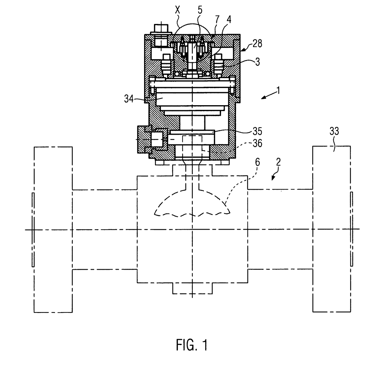
[0029]FIG. 1 shows a principle illustration of an electrical actuator 1 according to the present disclosure. This is provided for operating a ball valve. Of course, the electrical actuator may also be employed for other gears in the oil and natural gas industry, such as for example gate valves, chokes, blow-out-preventers or the like. Further, it is to be noted that in the embodiment according to FIG. 1, a rotational movement of the respective valve member 6 of the valve 2 is transferred, while in other electrical actuators, also an additional conversion of the rotational movement into a linear movement may be effec...


PUM


Abstract

An electrical actuator (1) especially for operating a valve (2) has at least one electric motor (3), a drive shaft (4) driven by the electric motor (3) and a gear shaft (5) rotatable by the drive shaft (4), which gear shaft is connected to a valve member (6) in a motion-transferring manner. Between the drive shaft (4) and the gear shaft (5), a return stop device (7) especially acting both ways in rotational direction is formed. This return stop device (7) has a pot-shaped outer part (8) and a hub part (9) rotatably supported therein. The hub part (9) is connected to the gear shaft (5) in a torque-proof manner and within at least one free space (10) between the hub part (9) and the outer part (8) a wedging member is arranged. This is only movement into free rolling position by the drive shaft (4) under a rotation of the drive shaft (4). The invention enables an improvement of an electrical actuator to the effect that this is provided with a so-called “fail as is”-device, while having a simple, reliable and cost-efficient construction and without the use of a stronger motor.

Description

CROSS-REFERENCE TO RELATED APPLICATION[0001]This National Stage Application claims priority to and benefit of PCT Application No. PCT / EP2012 / 003800, entitled “Electrical Actuator”, filed on Sep. 10, 2012, which is herein incorporated by reference in its entirety.FIELD OF THE DISCLOSURE[0002]This disclosure relates to an electrical actuator in particular, having a return stop device functioning in both ways.BACKGROUND[0003]Respective electrical actuators are known for example from the oil and gas industry for the operation of valves. Such valves include gate valves, chokes, ball valves, blow-out-preventers (BOP) or the like. In an application using the respective valves, an emergency measure is required in case of an energy failure, to adjust the valves to their closed or open position or alternatively secure the valves in their current position against the pressure of, for example, produced mineral oil. In this context, the two modes are referred to as “fail save close / open” and “fa...

Claims


Application Information

Patent Timeline
IPC IPC(8): F16K31/04
CPCF16K31/047F16K31/043F16K31/046Y10T74/2066
Inventor LENZ, NORBERT
Owner CAMERSON INT CORP
Why Eureka
Try Eureka