Device at an embroidery frame and method for clamping and tensioning a textile material

a technology of textile material and clamping frame, which is applied in the field of devices at embroidery frames for sewing machines, can solve the problems of high manual pressure, high cost of production of such tubes, and inability to achieve strong clamping of textiles before after, so as to facilitate initial clamping of textile materials and facilitate final tensioning of textile materials

Inactive Publication Date: 2005-06-07
KSIN LUXEMBOURG II
View PDF12 Cites 25 Cited by
  • Summary
  • Abstract
  • Description
  • Claims
  • Application Information

AI Technical Summary

Benefits of technology

[0011]According to another embodiment, the second height is substantially higher than the first height, whereby straightening of the at least one crease in the upper wall before straightening of the at least one crease in the lower wall is facilitated.
[0018]According to one aspect of a preferred embodiment, an end of the flange of the outer frame at the inner circumference of the outer frame is chamfered originating from an upper side of the flange and towards a lower side of the outer frame in a downward direction and towards an intended location of the inner frame, which end of the flange of the outer frame is designed to fit for bearing against an end of a lower flange at an outer circumference of the inner frame being chamfered originating from an upper side of the lower flange and towards a lower side of the lower flange in a downward direction and towards an inner circumference of the inner frame. Thereby, the inner and outer frames can be fit to each other and vertical forces between the inner frame and the outer frame can be received.

Problems solved by technology

Another problem with many of the embroidery frames on the market today is that they require that a high force is applied manually, since the tensioning of the textile material is performed totally manually.
One disadvantage with the device in accordance with U.S. Pat. No. 5,129,171 is that a strong clamping of the textile is not achieved before after the tensioning of the textile.
The cost of production of such a tube, inner frame and outer frame will thereby be high.

Method used


Image

  • Device at an embroidery frame and method for clamping and tensioning a textile material
  • Device at an embroidery frame and method for clamping and tensioning a textile material
  • Device at an embroidery frame and method for clamping and tensioning a textile material

Examples


Embodiment Construction

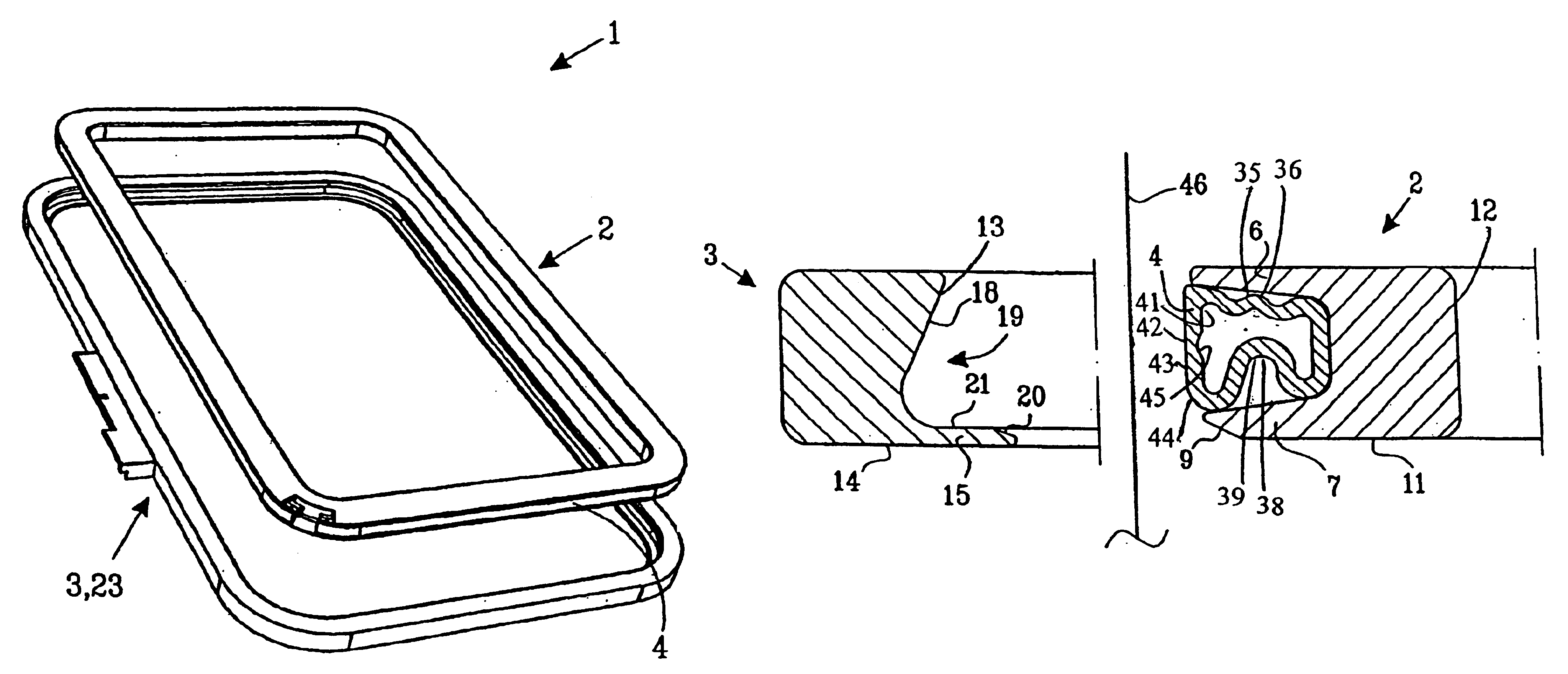
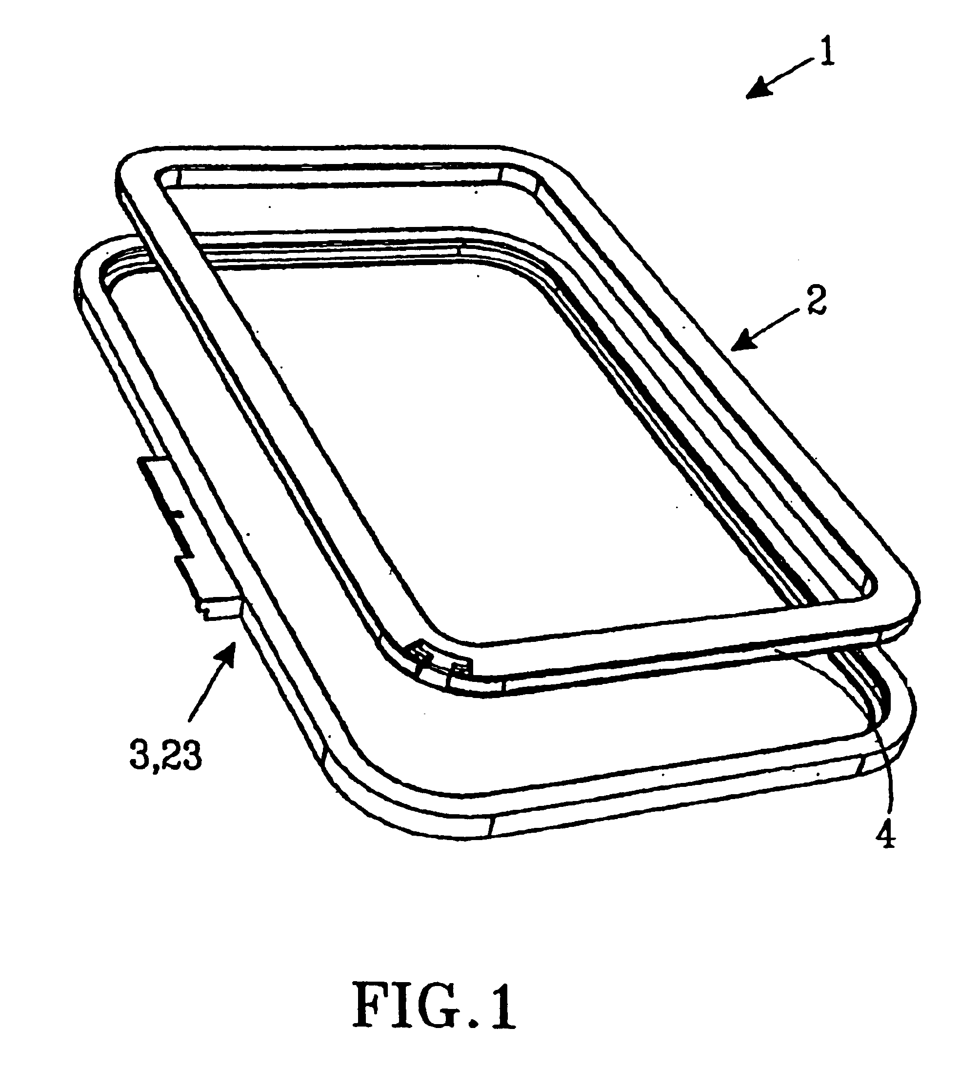
[0046]FIG. 1 shows a perspective view of an embroidery frame 1 of rectangular shape in accordance with a preferred embodiment. The embodiment of the embroidery frame 1 is intended to be used for fastening and tensioning a textile material for permitting embroidering on the textile material by a sewing machine. Furthermore, the embodiment of the embroidery frame 1 is intended to be mounted in an embroidery unit of a sewing machine. The embroidery frame 1 may be moved around by the embroidery unit in accordance with a pre-programmed pattern, whereby an embroidered pattern is created when stitches are placed on the textile material. The embodiment of the embroidery frame 1 includes an inner frame 2, an outer frame 3, 23 and a hose 4 arranged at the inner frame 2, which hose 4 is expandable by means of pressurization. The inner frame 2 and the outer frame 3, 23 have shapes that are adapted to each other in order to enable assembly of the inner frame 2 and the outer frame 3, 23 as well a...


PUM


Abstract

The present patent application relates to an embroidery frame for a sewing machine and a method for clamping and tensioning a textile material. The embroidery frame comprises an inner frame, an outer frame and a hose arranged between the inner frame and the outer frame, which hose is expandable through pressurization. After manual assembly of the inner frame and the outer frame, a textile material intended for embroidering can be clamped between the hose and the outer frame and tensioned over an area of the textile material intended for embroidering through pressurization of the hose. The hose expands through initial pressurization in an upper part and clamps thereby the textile material between the upper part of the hose and the outer frame. Upon continued pressurization the hose expands in a lower part in a direction towards the outer frame and tensions thereby the textile material.

Description

FIELD OF THE INVENTION[0001]The present invention relates to a device at an embroidery frame. More particularly, the present invention relates to a device at an embroidery frame for a sewing machine. The device includes an inner frame, an outer frame and a hose arranged between the inner frame and the outer frame. The hose is expandable through pressurization. Furthermore, the present invention also relates to a method for clamping and tensioning a textile material. More particularly, the present invention also relates to a method for clamping and tensioning a textile material in an embroidery frame for a sewing machine, wherein the embroidery frame includes an inner frame, an outer frame and a hose arranged between the inner frame and the outer frame, which hose is expanded through pressurization.BACKGROUND OF THE INVENTION[0002]When embroidering on a textile material it is desirable that the embroidery area of the textile material is kept as crease-free and as tensioned as possibl...

Claims


Application Information

Patent Timeline
Patent Type & Authority Patents(United States)
IPC IPC(8): D05C9/04D05C9/00D05C9/12
CPCD05C9/12D05C9/04
Inventor EKLOF, PETTERAREN, HERMANSVAHN, PER
Owner KSIN LUXEMBOURG II
Why Eureka
Try Eureka