Cross-connect jumper assembly having tracer lamp

a cross-connecting and jumper assembly technology, applied in the direction of incorrect coupling prevention, coupling device connection, electrical equipment, etc., can solve the problem of difficult to quickly determine which jack module is cross-connected together, visible from the front end

Inactive Publication Date: 2005-06-14
COMMSCOPE TECH LLC
View PDF23 Cites 140 Cited by
  • Summary
  • Abstract
  • Description
  • Claims
  • Application Information

AI Technical Summary

Problems solved by technology

Consequently, absent indicators, it is difficult to quickly determine which two jack modules are cross-connected together.
A problem with tracer lamp configurations as described above is that they are only visible from the front ends of the jack modules.

Method used


Image

  • Cross-connect jumper assembly having tracer lamp
  • Cross-connect jumper assembly having tracer lamp
  • Cross-connect jumper assembly having tracer lamp

Examples


Embodiment Construction

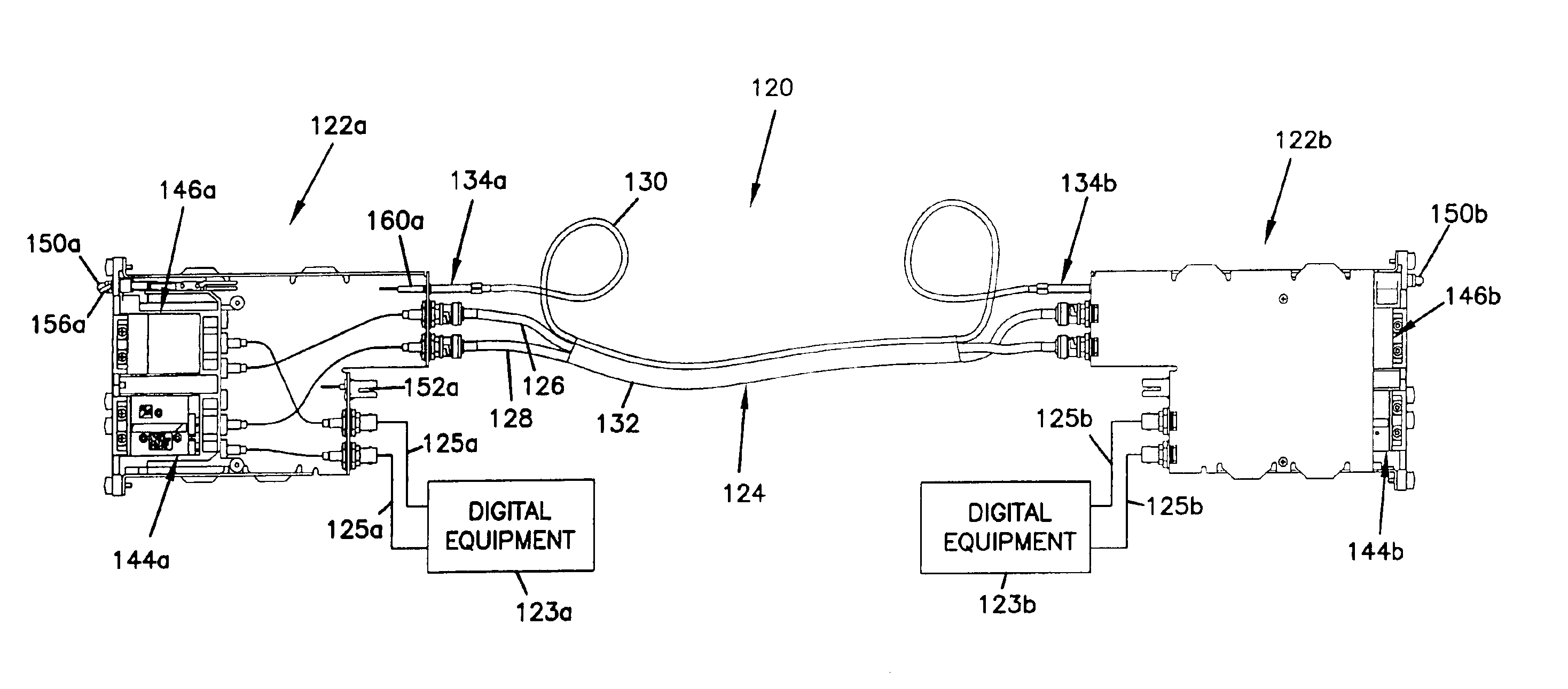
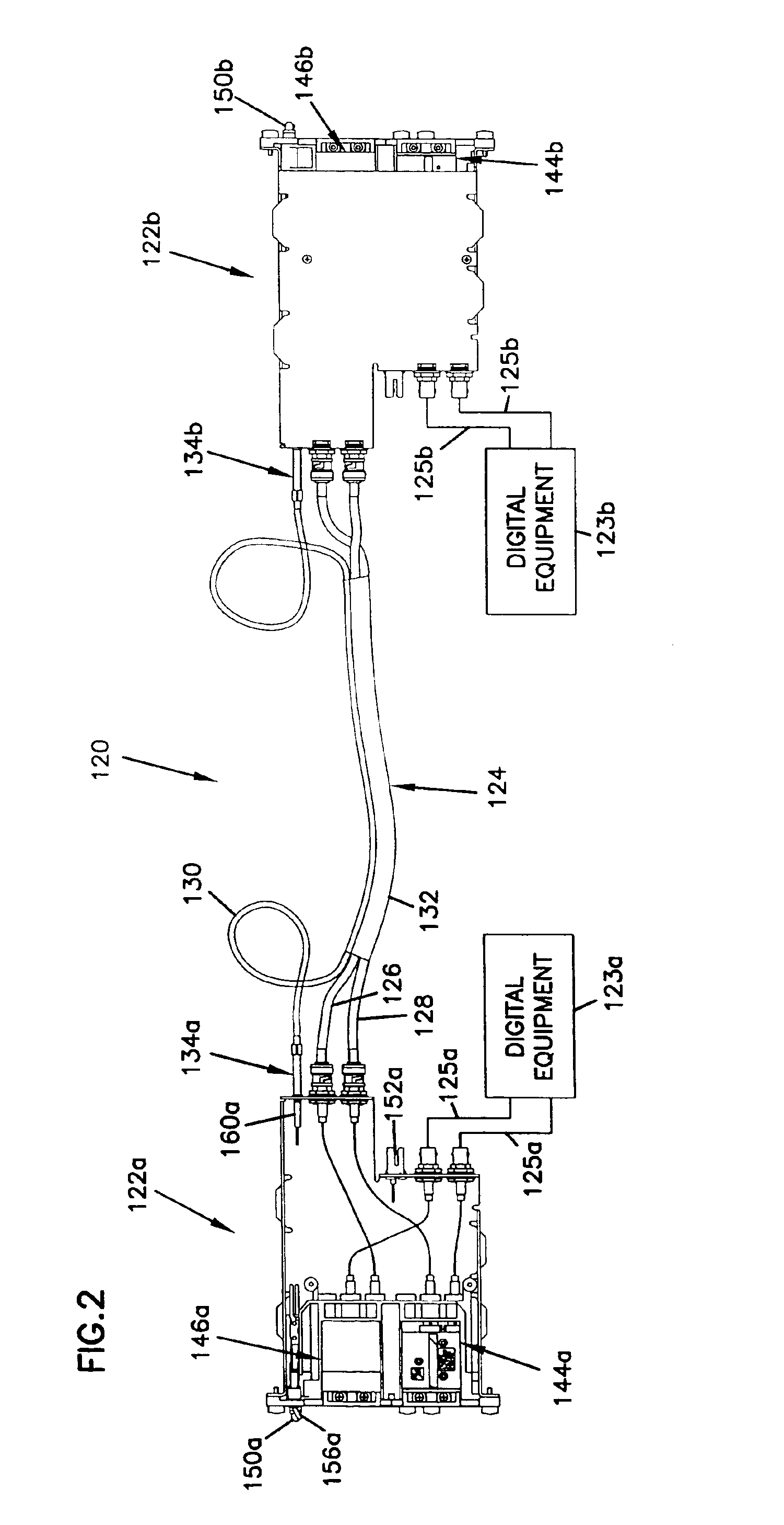
[0025]FIG. 2 illustrates a digital cross-connect (DSX) system 120 that is an example of how certain inventive aspects in accordance with the principles of the present disclosure can be practiced. The DSX system 120 includes DSX modules 122a, 122b electrically connected to pieces of telecommunications equipment 123a, 123b by cables 125a, 125b (e.g., co-axial cables). The pieces of telecommunications equipment 123a, 123b are electrically connected to one another by a jumper assembly 124 that provides a cross-connection between the DSX modules 122a, 122b. The DSX modules 122a, 122b include tracer lamps (e.g., LED's 150a, 150b) that are visible from front ends of the modules 122a, 122b. The jumper assembly 124 includes tracer lamp assemblies 134a, 134b that are visible from rear ends of the modules 122a, 122b.

[0026]Referring to FIGS. 2 and 3, the DSX modules 122a, 122b include IN switching jacks 144a, 144b and OUT switching jacks 146a, 146b that provide a means for temporarily breaking...


PUM


Abstract

A jumper assembly for a DSX system is disclosed herein. The jumper assembly includes a messenger wire for electrically connecting tracer lamp circuits corresponding to two cross-connected DSX modules. The jumper assembly also includes tracer lamp devices carried with the messenger wire.

Description

[0001]This application is a continuation of U.S. patent application Ser. No. 10 / 219,809, filed Aug. 14, 2002, and issued as U.S. Pat. No. 6,743,044. U.S. patent application Ser. No. 10 / 219,809 is incorporated herein by reference.FIELD OF THE INVENTION[0002]The present invention relates generally to digital cross-connect equipment. More particularly, the present invention relates to cross-connect switching systems having tracer lamp circuits.BACKGROUND OF THE INVENTION[0003]In the telecommunications industry, the use of switching jacks to perform digital cross-connect (DSX) and monitoring functions is well known. The jacks may be mounted to replaceable cards or modules, which in turn may be mounted in a chassis, and multiple chassis may be mounted together in an equipment rack. Modules for use in co-axial environments are described in U.S. Pat. No. 5,913,701, which is incorporated herein by reference. Modules for use in twisted pair applications are described in U.S. Pat. No. 6,116,9...

Claims


Application Information

Patent Timeline
Patent Type & Authority Patents(United States)
IPC IPC(8): H01R13/641H01R13/64
CPCH01R13/641Y10S439/91
Inventor MUSOLF, BRUCEGOOD, THOMASDEMULLING, RICHARD T.BURROUGHS, DENNIS
Owner COMMSCOPE TECH LLC
Why Eureka
Try Eureka