Toilet seat lifter with flusher

a technology of toilet seat and flusher, which is applied in the direction of flushing device, water installation, construction, etc., can solve the problems of increasing the complexity of electrical and compressed air systems, increasing repair and maintenance costs, and impracticality or undesirable use of electrical or compressed air in toilet facilities, particularly commercial toilet facilities

Inactive Publication Date: 2005-06-21
STEMEN ROBERT W
View PDF25 Cites 31 Cited by
  • Summary
  • Abstract
  • Description
  • Claims
  • Application Information

AI Technical Summary

Benefits of technology

[0005]According to a preferred embodiment of the present invention, a toilet seat raising mechanism, that is for operation with a toilet having a seat, has an input line and a first control that causes a first change in a pressure in the input line from a first pressure level to a second pressure level in response to a first activation input. The toilet seat raising mechanism further has a seat actuator adapted for moving a toilet seat between a lowered position and a raised position in response to changes in the pressure in the input line. The seat actuator places the toilet seat in the lowered position when the pressure is at the first pressure level and the seat actuator places the toilet seat in the raised position when the pressure is at the second pressure level. The toilet seat raising mechanism also has a second control that operates in response to a second input to selectively place the input line in communication with a drain so as to cause a second change in the pressure from the second pressure level towards the first pressure level. The toilet seat raising mechanism also has a flush actuator for flushing a toilet in response to an operation of the second control.

Problems solved by technology

The use of electrical or compressed air in toilet facilities, particularly commercial toilet facilities, is often impractical or undesirable for a number of reasons.
First, the cost for electrical and compressed air equipment is expensive.
Second, the complexity of electrical and compressed air systems increase repair and maintenance costs.
Third, the placement of electrical power near plumbing fixtures is dangerous and increases the likelihood of electrical shock.
Fourth, fixtures or other devices that are used to automatically lift and / or lower toilet seats are required to operate in wet and often dirty conditions which severely limits design options.
The contention between men and women of “who left the seat up?” is often a source of disagreement.
The problem with returning the toilet seat to its lowered position after toilet use is that manually doing so is easily forgotten and typically avoided to eliminate contact with toilet fixtures.

Method used


Image

  • Toilet seat lifter with flusher
  • Toilet seat lifter with flusher
  • Toilet seat lifter with flusher

Examples


Embodiment Construction

[0012]It is important to note, that these embodiments are only examples of the many advantageous uses of the innovative teachings herein. In general, statements made in the specification of the present application do not necessarily limit any of the various claimed inventions. Moreover, some statements may apply to some inventive features but not to others. In general, unless otherwise indicated, singular elements may be in the plural and visa versa with no loss of generality.

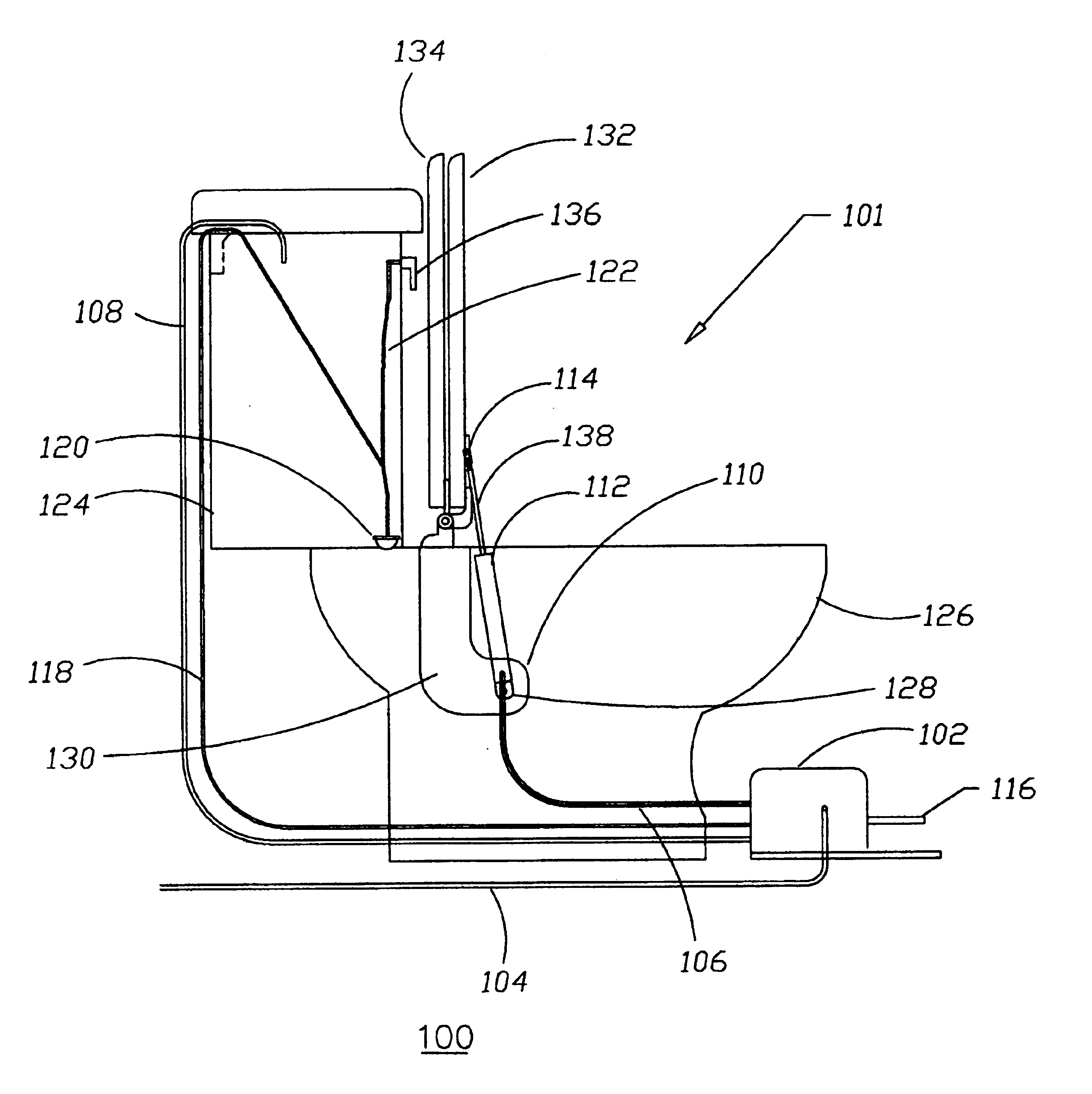
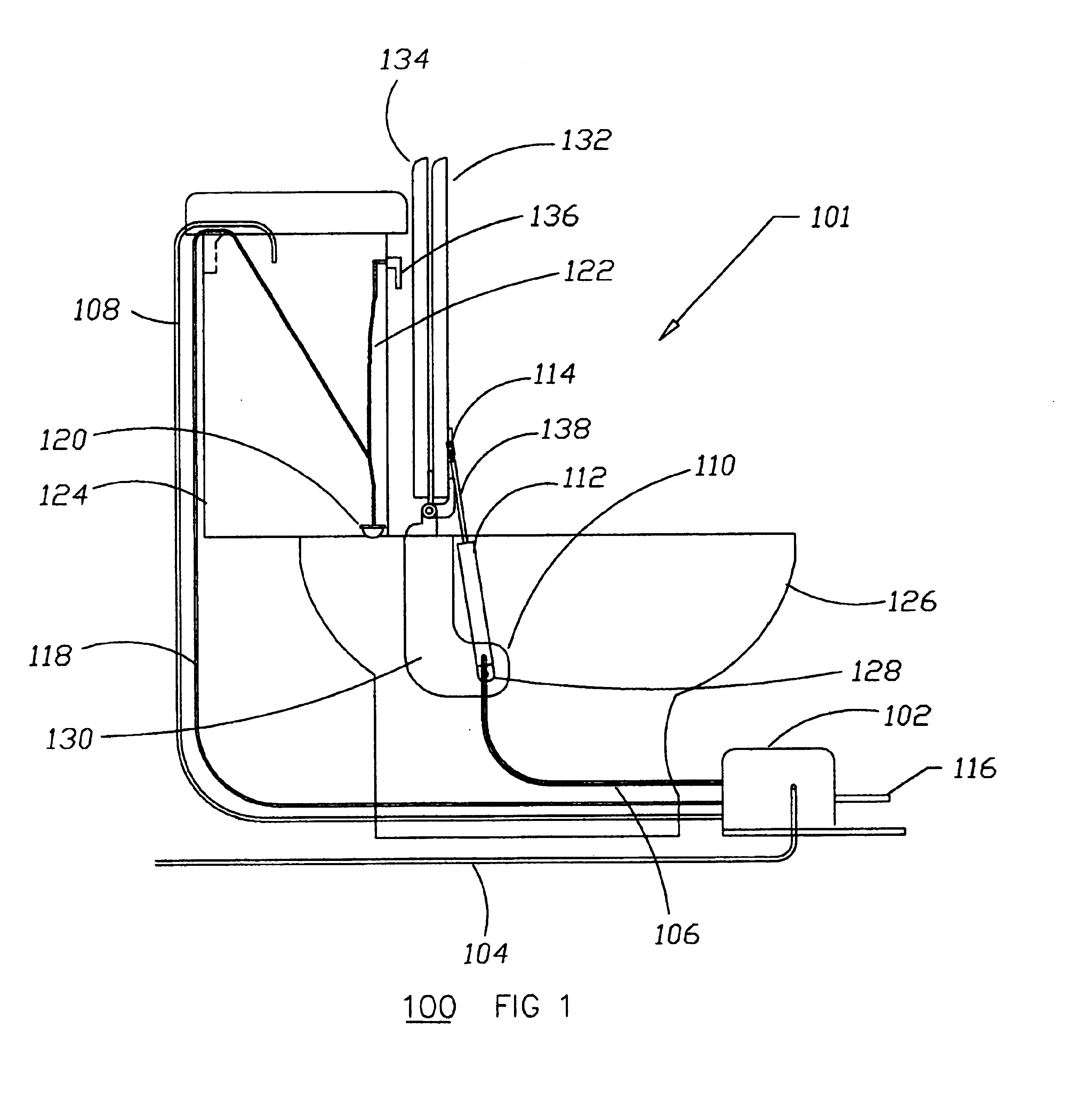
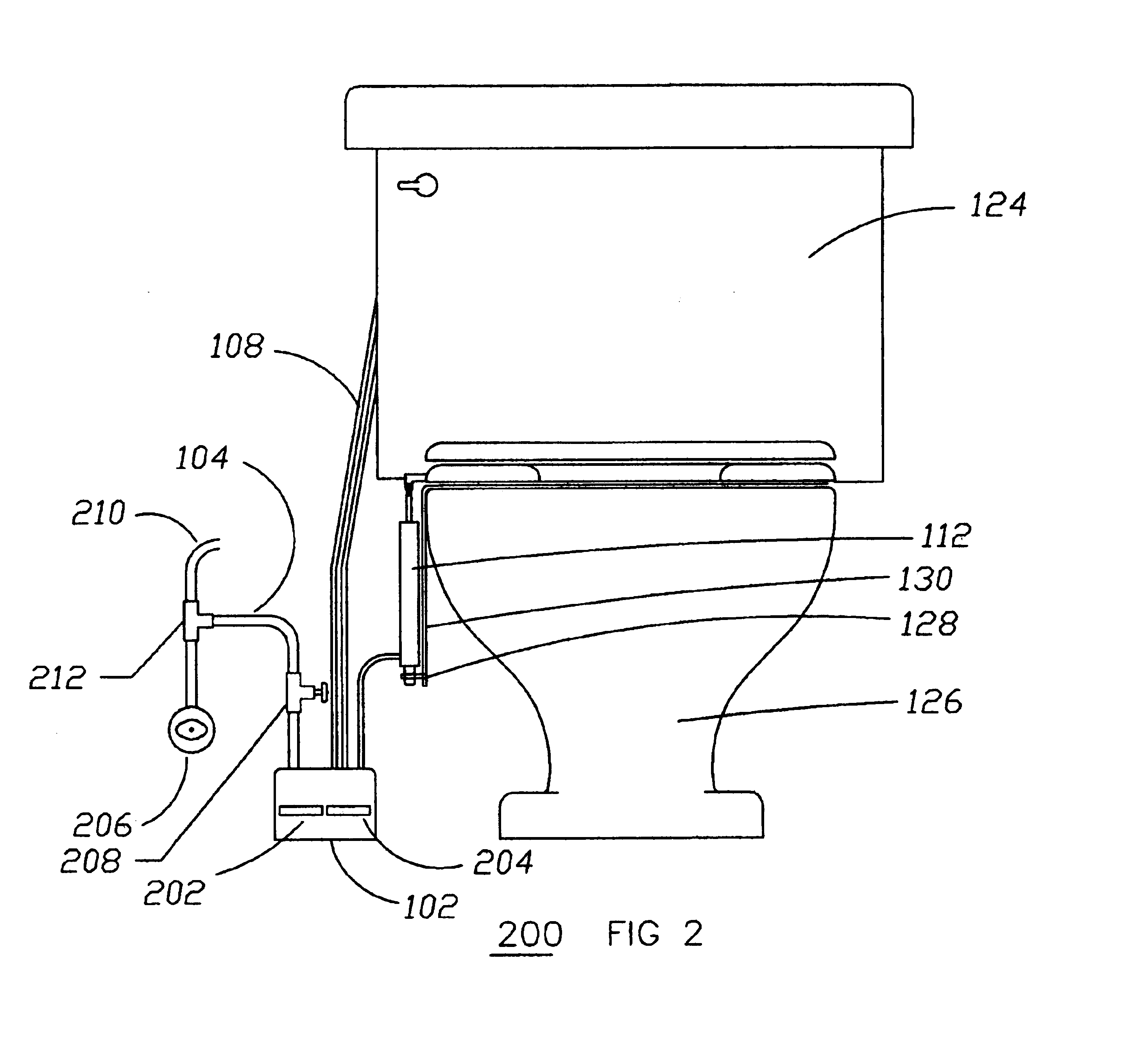
[0013]The present invention, according to an exemplary embodiment, overcomes problems with the prior art by providing a toilet seat lifting mechanism that includes foot operated valves that control the flow of water to a hydraulic cylinder that operates to lift and lower a toilet seat. Water from the water supply to the toilet is connected, in response to a user's operation of a valve, to the hydraulic cylinder to provide energy to lift the toilet seat. The user subsequently operates another valve that causes t...


PUM


Abstract

A mechanism for raising and lowering a toilet seat in response to actuation of foot pedals. An actuation cylinder with a contained piston is connected between the toilet bowl and the toilet seat. Water from the supply line for the toilet is routed to the actuator cylinder when a seat up pedal is depressed and causes the piston to extend out of the actuation cylinder and raise the seat. Operation of a flush pedal causes the water within the actuation cylinder to drain so that the toilet seat lowers. A mechanical linkage from the flush pedal to the flush mechanism of the toilet links toilet flushing to the seat lowering action, ensuring that the seat is lowered after each flush.

Description

FIELD OF THE INVENTION[0001]The present invention generally relates to the field of toilet seat lifting mechanisms and more particularly to a toilet seat lifting mechanism that combines toilet flushing and seat lowering.BACKGROUND OF THE INVENTION[0002]Allowing one to use toilet facilities while avoiding hand contact with the toilet seat or other fixtures associated with the toilet facilities enhancing sanitary conditions. Health problems due to unsanitary practices are well understood. In order to eliminate the need to contact toilet fixtures, several electrical and compressed air solutions have been developed. The use of electrical or compressed air in toilet facilities, particularly commercial toilet facilities, is often impractical or undesirable for a number of reasons. First, the cost for electrical and compressed air equipment is expensive. Second, the complexity of electrical and compressed air systems increase repair and maintenance costs. Third, the placement of electrical...

Claims


Application Information

Patent Timeline
Patent Type & Authority Patents(United States)
IPC IPC(8): A47K13/10
CPCA47K13/10
Inventor STEMEN, ROBERT W.
Owner STEMEN ROBERT W
Why Eureka
Try Eureka