
Sewing machine

a sewing machine and sewing technology, applied in the field of sewing machines, can solve the problems of forcing the operator into useless labor and tim

Active Publication Date: 2005-06-21
BROTHER KOGYO KK
View PDF14 Cites 7 Cited by
  • Summary
  • Abstract
  • Description
  • Claims
  • Application Information

AI Technical Summary

Benefits of technology

[0013]In the above-described construction, the sewing machine preferably further comprises a thread holder holding the thread drawn by the thread drawing member. In this case, an amount of thread extending from the needle eye to the thread end held by the holder is set so as to be approximately equal to an amount of thread extending from the needle eye to the thread end held by the thread holder.
[0014]Furthermore, the sewing machine prefer

Problems solved by technology

Consequently, the operator is forced into useless labor and time.

Method used


Image

  • Sewing machine
  • Sewing machine
  • Sewing machine

Examples


Embodiment Construction

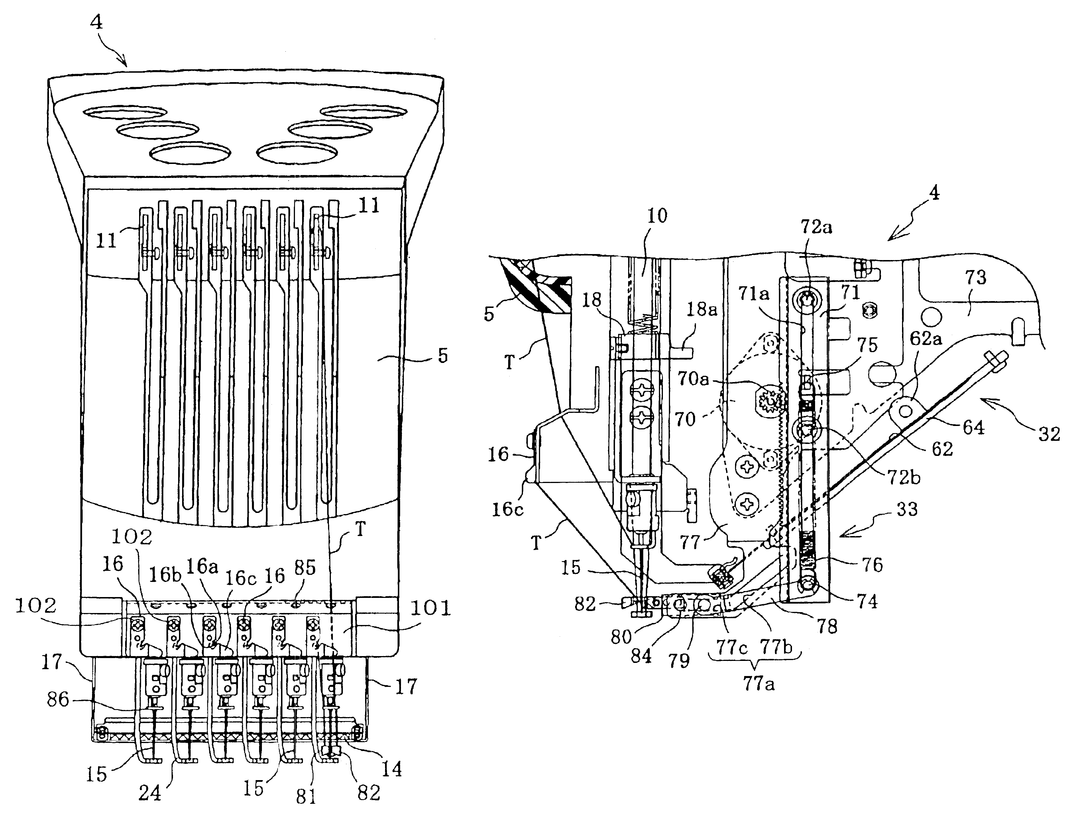
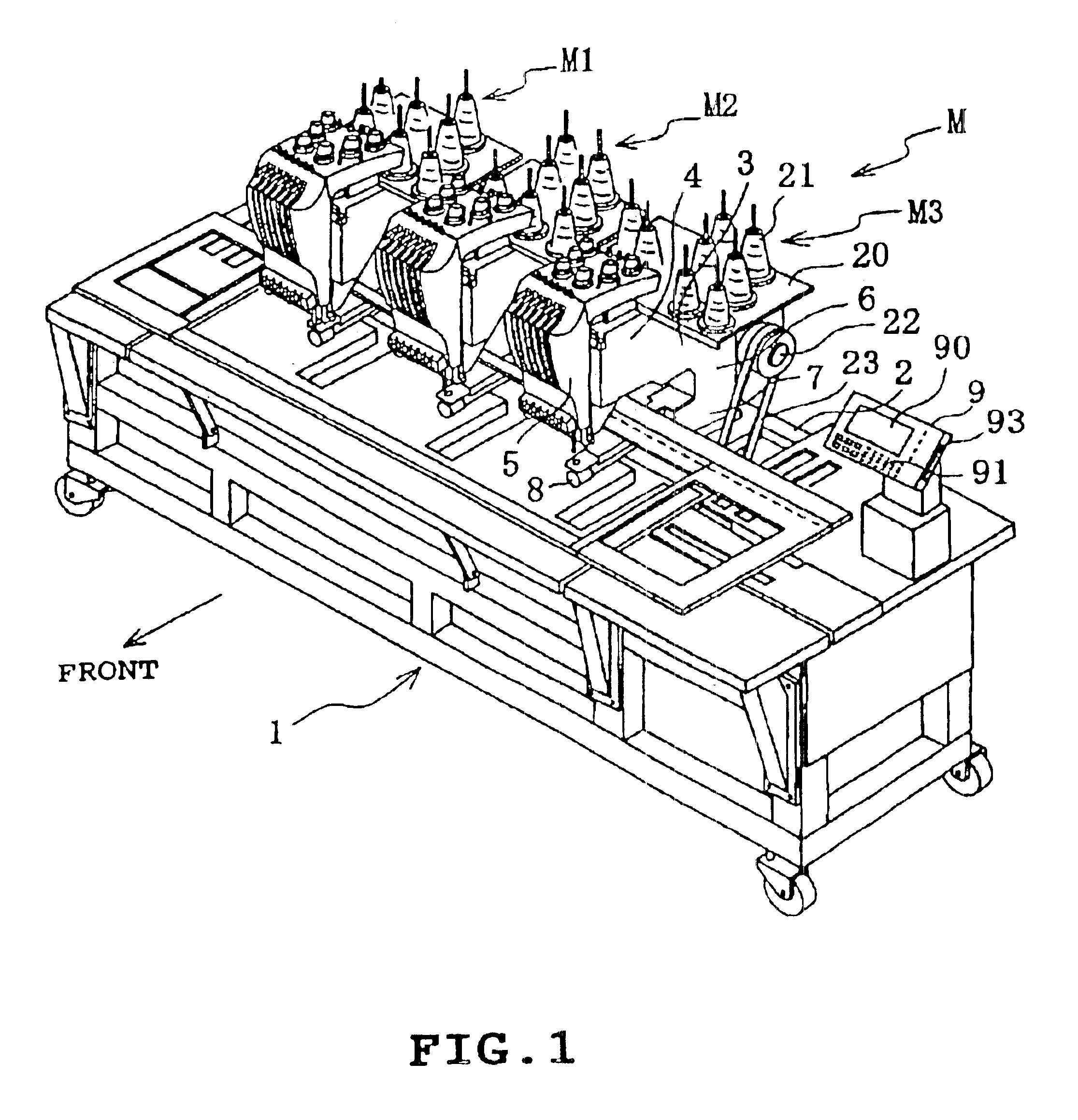
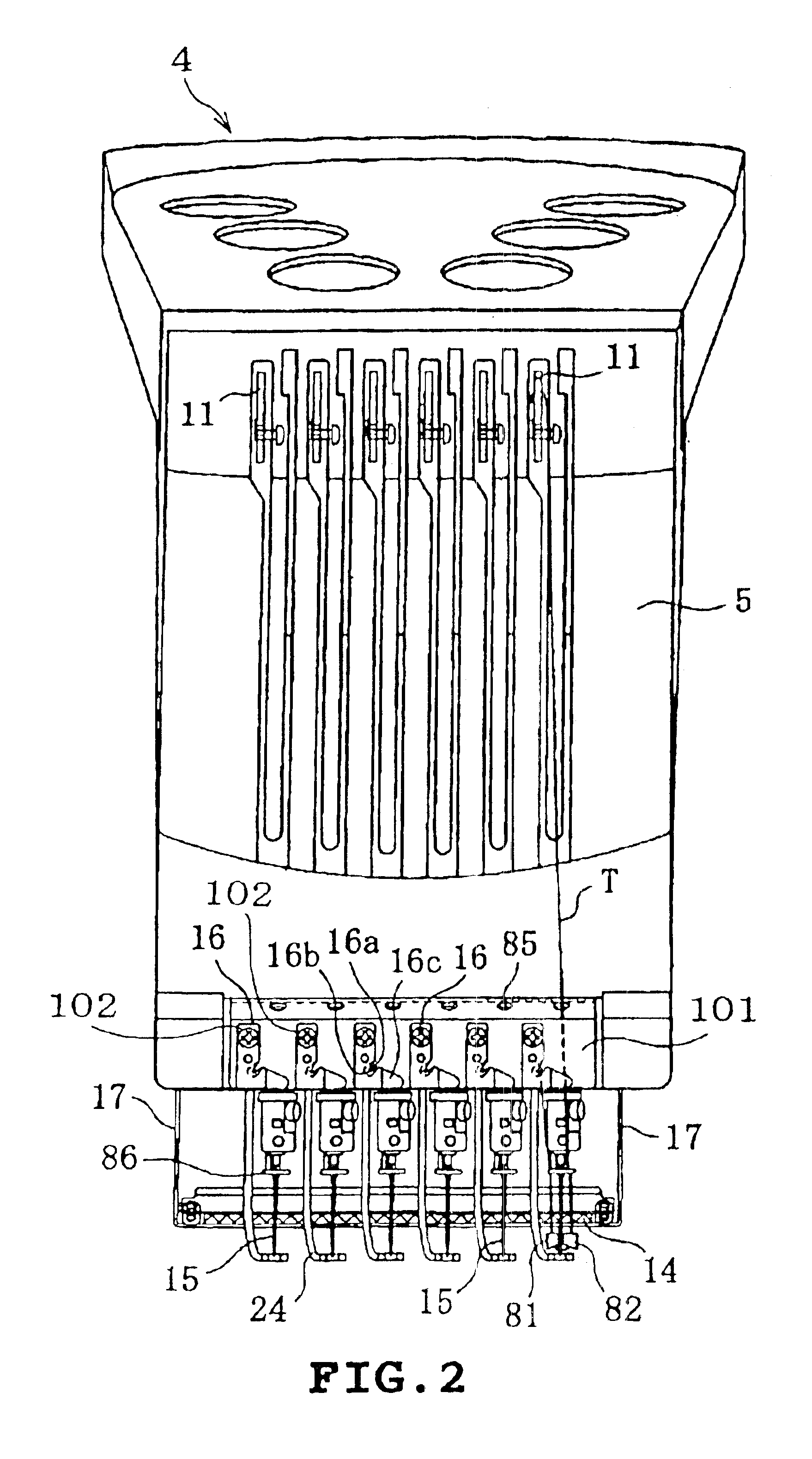
[0027]One embodiment of the present invention will be described with reference to the drawings. In the embodiment, the invention is applied to an industrial or occupational multi-head sewing machine including three multi-needle embroidery sewing machines which can embroider three same embroidery patterns on respective caps at the same time.

[0028]The multi-head sewing machine M will first be described. Referring to FIG. 1, the multi-head sewing machine M comprises an embroidering machine body frame 1 extending in the right-and-left direction, and a generally rectangular machine support plate 2 mounted on the rear top of the frame 1 so as to extend in the right-and-left direction. Three multi-needle embroidery sewing machines M1 to M3 are mounted on the support plate 2 so as to be juxtaposed in the right-and-left direction. The embroidery sewing machines M1 to M3 have the same structure.

[0029]Each of the embroidery sewing machines M1 to M3 includes an arm 3 having a distal end on whic...


PUM


Abstract

A sewing machine includes a head on which a needle bar for fixing a needle is mounted, a thread cutting blade mounted in the head so as to be capable of cutting an end of a thread which is threaded so as to be passed through an eye of the needle, and a holder mounted in the head so as to be capable of holding the thread end after the thread end has been cut by the thread cutting blade. The thread cutting blade is positioned so that a first amount of thread from the eye of the needle mounted in the head to the thread end held by the holder equals a second amount of thread by which the thread end is drawn to an underside of a cloth in a stitch formed immediately after start of a sewing operation.

Description

BACKGROUND OF THE INVENTION[0001]1. Field of the Invention[0002]This invention relates to sewing machines, and more particularly to a sewing machine in which a thread end is drawn to an underside of a cloth in a stitch immediately after start of sewing.[0003]2. Description of the Related Art[0004]There have conventionally been proposed sewing machines provided with threading means for automatically threading a sewing needle. For example, JP-8-173676-A discloses a technique for catching a thread by a hook having been passed through an eye of the needle and returning the hook through the needle eye such that the needle thread is passed through the needle eye, while the thread is guided by thread guide grooves or the like and held by thread holders. JP-51-24353-A discloses a first nipper holding a thread cut during the sewing and a second nipper catching the thread held by the first nipper. The thread caught by the second nipper is passed through the needle eye by a thread extruder. Th...

Claims


Application Information

Patent Timeline
IPC IPC(8): D05B65/06D05B65/00D05B87/00D05B87/02D05B65/02D05B53/00
CPCD05B65/06D05B87/02
Inventor NOGUCHI, YASUKAZUKAWAGUCHI, YASUHIKOKATO, MASATO
Owner BROTHER KOGYO KK
Learn More