
Fastener lockout device

a technology of fastener and lockout device, which is applied in the direction of anti-theft device, anti-theft cycle device, cycle equipment, etc., can solve the problems of increasing the incidence of theft of these items

Inactive Publication Date: 2005-06-28
SWANSON RICHARD C
View PDF13 Cites 22 Cited by
  • Summary
  • Abstract
  • Description
  • Claims
  • Application Information

AI Technical Summary

Problems solved by technology

As the popularity of expensive tires and expensive alloy rims has increased, the incidence of theft of these items has also increased.

Method used


Image

  • Fastener lockout device
  • Fastener lockout device

Examples


Embodiment Construction

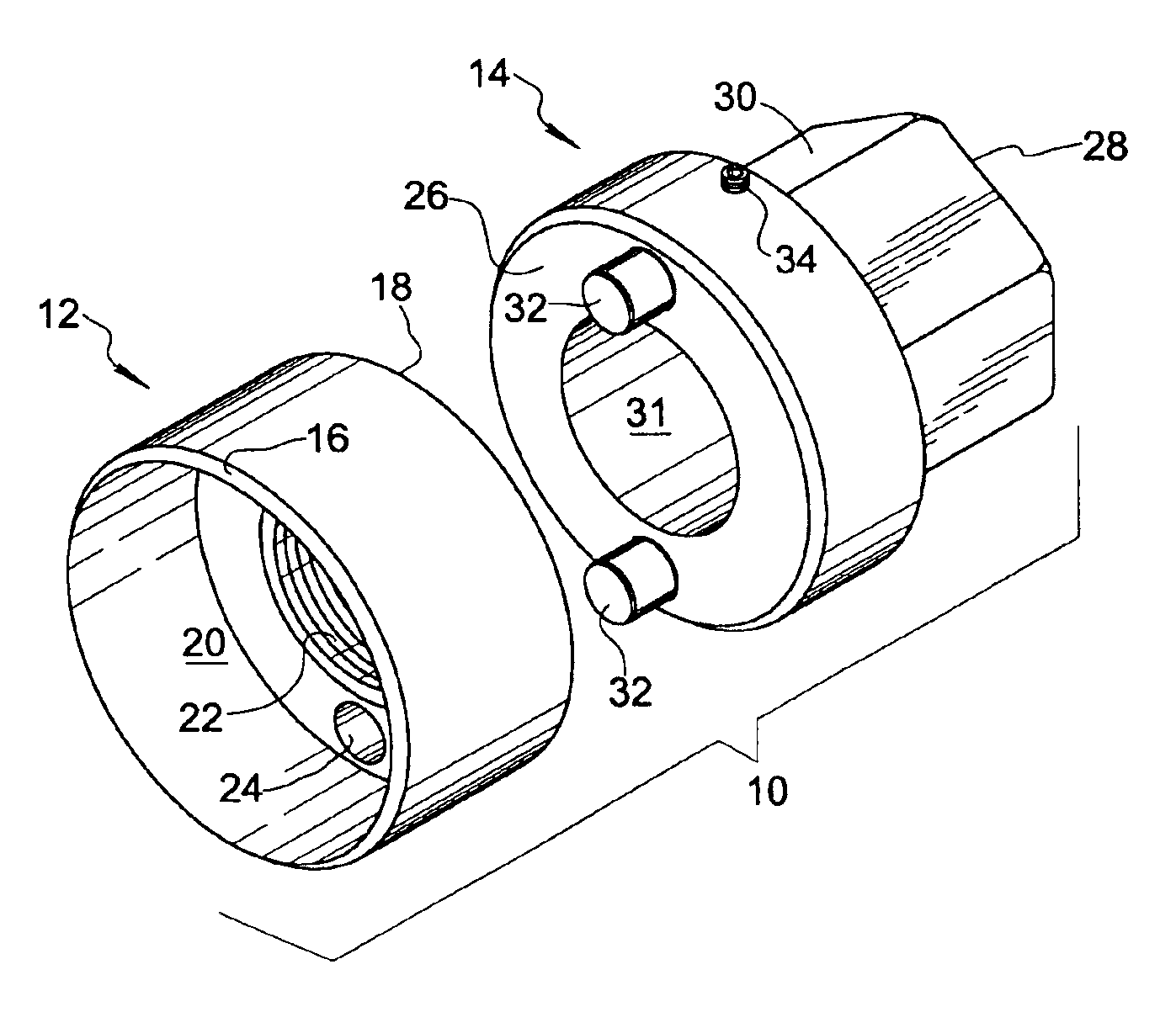
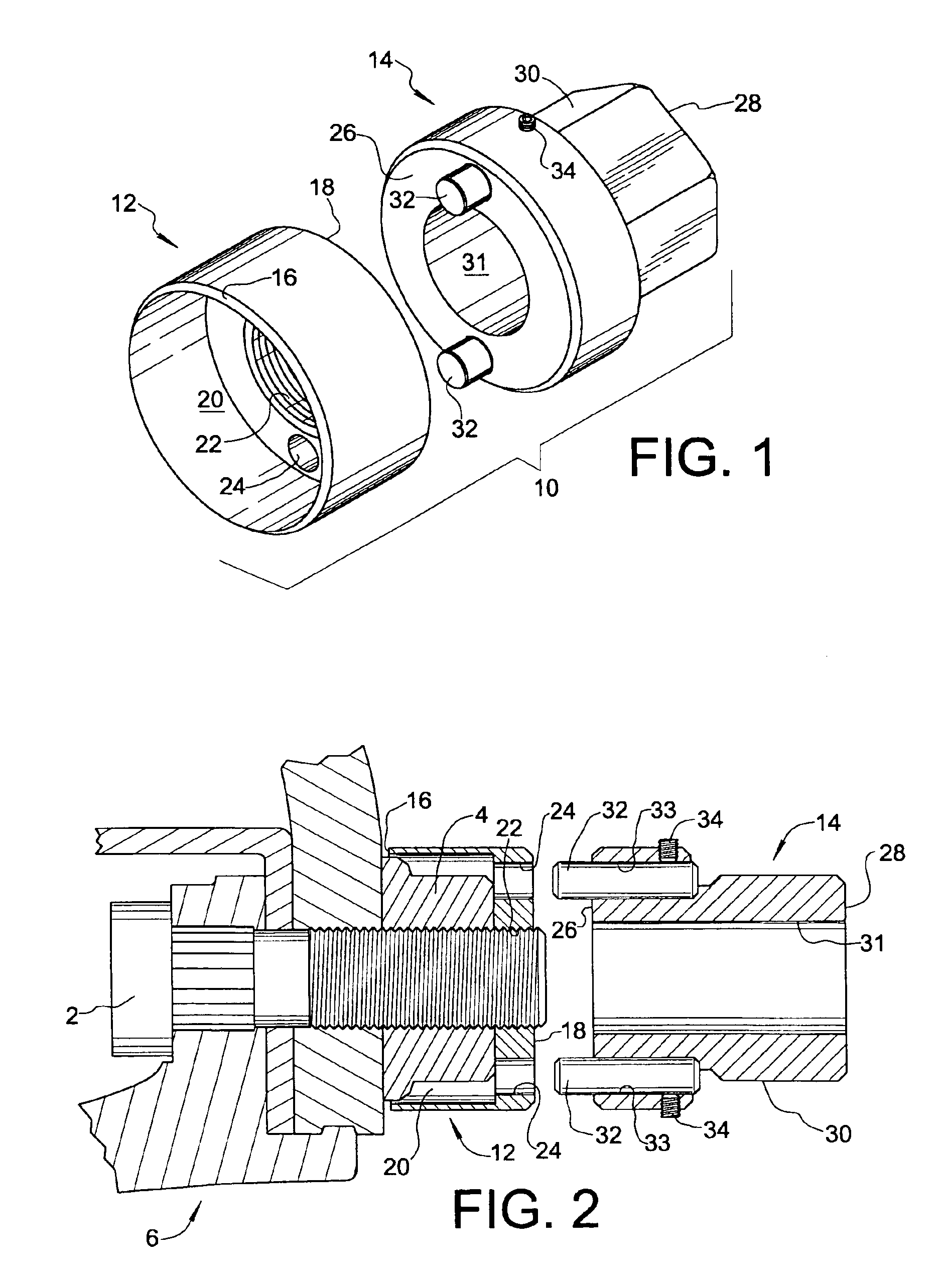
[0009]Referring initially to FIG. 1 of the drawings, a fastener lockout device in accordance with an embodiment of the present invention is shown and identified broadly by the reference numeral 10. Lockout device 10 generally comprises a cap 12 and a corresponding adapter 14 for use with cap 12.

[0010]Cap 12 is preferably in the form of a smooth cylindrical body and includes a first end 16 and a second end 18 opposite the first end. First end 16 opens into a hollow portion 20 for receiving a lug nut, and a threaded hole 22 extends in an axial direction from hollow portion 20 through the second end 18 of cap 12. The second end 18 of cap 12 is configured for end-to-end coupling with adapter 14, with the particular configuration being open to a wide variety of alternatives for enabling torque to be transmitted from the adapter to the cap. In the depicted embodiment, a pair of pin holes 24 (only one being visible in FIG. 1) are provided through second end 18 to hollow portion 20 for rece...


PUM


Abstract

A lockout device for restricting access to a nut through which a stud passes in threaded engagement with the nut comprises a cylindrical cap and a corresponding adapter. The cap includes first and second opposite ends and has a hollow portion opening through the first end of sufficient size for receiving most or all of the nut. A threaded hole sized for threaded engagement with the stud extends in an axial direction through the second end of the cap to communicate with the cap's hollow portion. The adapter includes a leading end and a trailing end, and has a hexagonal configuration adjacent its trailing end and an axially extending stud hole through its leading end sized to accommodate the stud. The second end of the cap and the leading end of the adapter are configured for end-to-end coupling with one another, such as by providing pin holes and corresponding pins, to enable torque to be transmitted from the adapter to the cap while the cap is in threaded engagement with the stud. The invention has utility for preventing theft of heavy duty truck and vehicle wheels.

Description

FIELD OF THE INVENTION[0001]The present invention relates generally to fastener security devices, and more particularly to a fastener lockout device useful for example in deterring vehicle wheel and wheel rim theft.BACKGROUND OF THE INVENTION[0002]Lug nuts used to secure wheels and wheel rims on heavy trucks, buses, trailers, recreational vehicles, or the like are threadably mated with corresponding studs extending through the wheel hub to provide a clamping force. As the popularity of expensive tires and expensive alloy rims has increased, the incidence of theft of these items has also increased.[0003]Heretofore, anti-theft nuts have been proposed for use, whereby the user removes an existing conventional nut and replaces the conventional nut with a specially designed ant-theft nut that requires a special key or adapter for application of torque to the anti-theft nut. See, for example, U.S. Pat. Nos. 4,742,702 and 4,897,008. Newer truck wheel systems require a large clamping force ...

Claims


Application Information

Patent Timeline
Patent Type & Authority Patents(United States)
IPC IPC(8): F16B41/00
CPCF16B41/005Y10T70/5836Y10T70/5867
Inventor SWANSON, RICHARD C.
Owner SWANSON RICHARD C
Learn More