
Defect protecting circuit and a method for data slicer in an optical drive

a technology of data slicer and protection circuit, which is applied in the field of defect protection circuit and a data slicer protection method, can solve the problems that the data slicer in the dvd drive is still in the normal gain and the time period of data fault cannot be effectively reduced, so as to reduce incorrect data and reduce output data jitter.

Inactive Publication Date: 2005-07-05
TIAN HLDG
View PDF7 Cites 8 Cited by
  • Summary
  • Abstract
  • Description
  • Claims
  • Application Information

AI Technical Summary

Benefits of technology

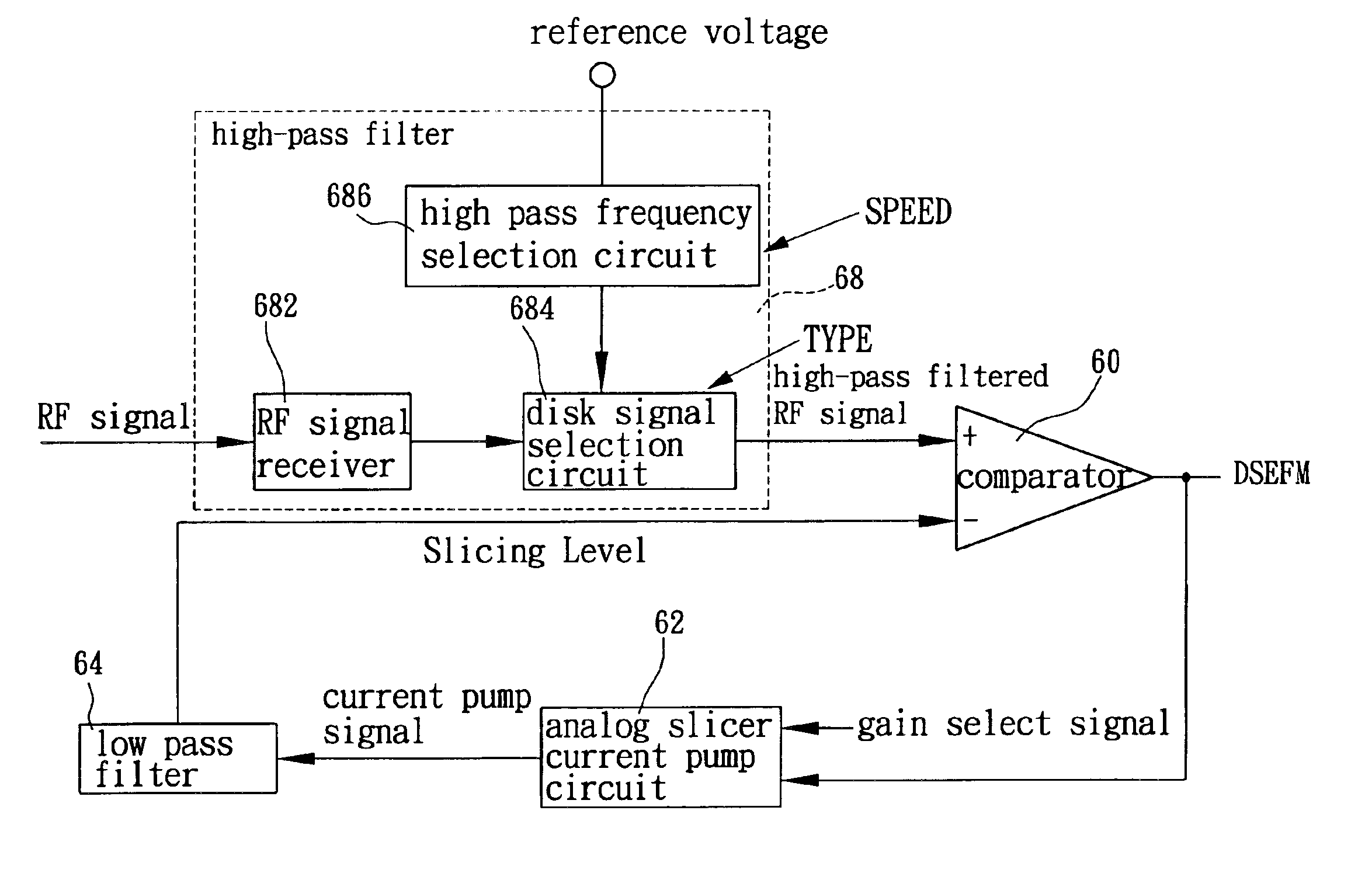
[0006]Accordingly, the primary object of the present invention is to provide a defect protecting circuit and a method for data slicer. When a defect occurs in a compact disk, the data slicer is switched from a mode of normal gain into a mode of high gain. After the defect does not occur further, the operation mode is switched back to a normal gain. Therefore, after the defect does not occur further, the slicing level can rapidly return back to a correct slicing level for reducing incorrect data caused by the defect, and the jitter in the output data is also reduced.
[0007]To achieve above objects, the present invention provides a defect protecting circuit and a method for data slicer. When a defect is detected, through the operation and comparing of the gain control logic circuit, a gain select signal is generated to switch gain of the data slicer so that a proper slicing level is acquired. When the defect terminates, then the data slicer will return back to a correct data slicer rapidly for reducing the jitter of the outputting data.

Problems solved by technology

Currently, when defect in the compact disk is detected, the data slicer in the DVD drive is still in the normal gain.
As a result, when the defect comes to an end, the data slicer can not chase to a correct slicing level so that the time period of data fault can not be reduced effectively.

Method used


Image

  • Defect protecting circuit and a method for data slicer in an optical drive
  • Defect protecting circuit and a method for data slicer in an optical drive
  • Defect protecting circuit and a method for data slicer in an optical drive

Examples


Embodiment Construction

[0017]The present invention relates to a defect protecting circuit and a method for data slicer. In the present invention, when a defect of the compact disk is detected, a gain adjusting mode is used for switching from a normal gain to a high gain. Then, after the defect terminates, the gain is switched back to the normal gain. Therefore, the slicing level of the data slicer can come back to the correct slicing level rapidly for reducing the number of incorrect data after defect occurring and the jitter in the output data is also reduced.

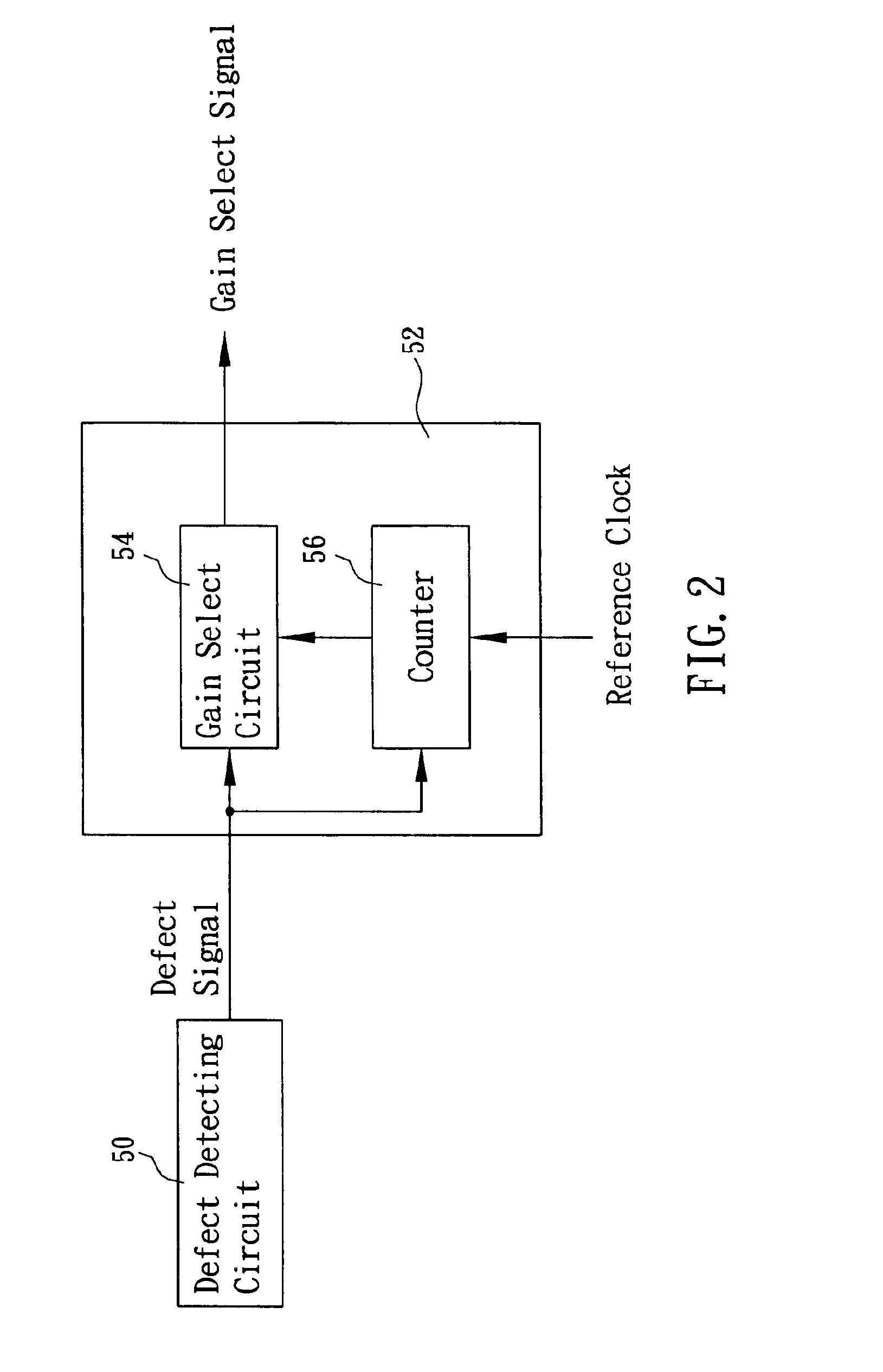
[0018]Referring to FIG. 2, which shows the block diagrams of the defect detection and gain control logic circuit. A defect detecting circuit 50 is connected to a gain control logic circuit 52. The gain control logic circuit 52 includes a gain select circuit 54 and a counter 56. The defect detecting circuit 50 serves to detect any defect existed in the compact disk. The input of the gain control logic circuit 52 is connected to the output of the defe...


PUM


Abstract

A defect protecting circuit and a method for data slicer in an optical drive is disclosed. As a defect occurs in a disk, the gain of the data slicer is switched to a high gain. After the defect does not occur further, the gain is switched back to a normal gain. Therefore the slicing level can return back to a correct slicing level for reducing incorrect data after the defect terminates, and the jitter in the output data is also reduced.

Description

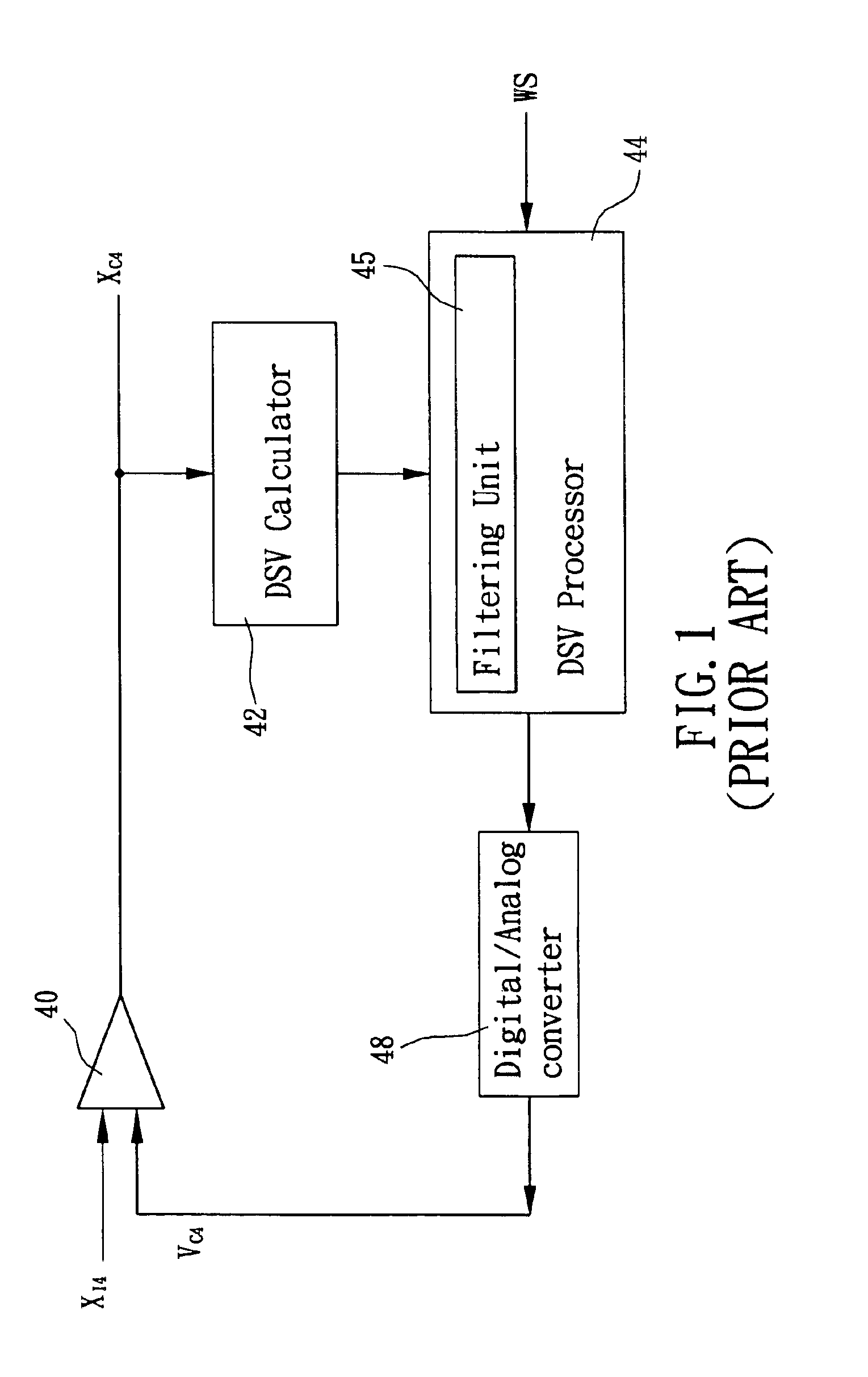
FIELD OF THE INVENTION[0001]The present invention relates to a defect protecting circuit and a method for data slicer by switching between a high gain and a normal gain, so that the incorrect data number may be reduced after occurring defect.BACKGROUND OF THE INVENTION[0002]Due to progress in photoelectric technology, digital audio and video technology can be used to acquire a high quality image and sound effects. Therefore, DVD (digital versatile disk) drives are nowadays widely used. Currently, when defect in the compact disk is detected, the data slicer in the DVD drive is still in the normal gain. As a result, when the defect comes to an end, the data slicer can not chase to a correct slicing level so that the time period of data fault can not be reduced effectively. Therefore, the above mentioned technology is highly needed to be improved.[0003]For the data slicer technology, one of the prior art is illustrated in FIG. 1. In FIG. 1, a comparator 40 compares the signals XI4 with...

Claims


Application Information

Patent Timeline
IPC IPC(8): G11B20/10G11B7/005G11B7/00
CPCG11B7/005G11B20/10009G11B2020/1457
Inventor CHOU, SUE-HONGLAI, YI-LIN
Owner TIAN HLDG
Learn More