
Coupler for a flexible tube

a flexible tube and coupling technology, applied in the field of couplings, can solve the problems of only possible techniques, patient injury or death, and additional trauma to the patien

Active Publication Date: 2005-07-12
MEDICAL COMPONENTS INC
View PDF10 Cites 87 Cited by
  • Summary
  • Abstract
  • Description
  • Claims
  • Application Information

AI Technical Summary

Problems solved by technology

However, this technique is only possible in cases where the catheter is of a relatively small diameter, made of a stiff material, and not significantly larger than the guide wire, for example, for insertion of small diameter dual lumen catheters.
The subcutaneous tunnel provides a stable anchor to prevent the proximal end of the catheter from moving and possibly becoming dislodged, which could result in patient injury or death.
The removal of the failed catheter assembly and the insertion of the new catheter assembly causes additional trauma to the patient, which is not desired.

Method used


Image

  • Coupler for a flexible tube
  • Coupler for a flexible tube
  • Coupler for a flexible tube

Examples


Embodiment Construction

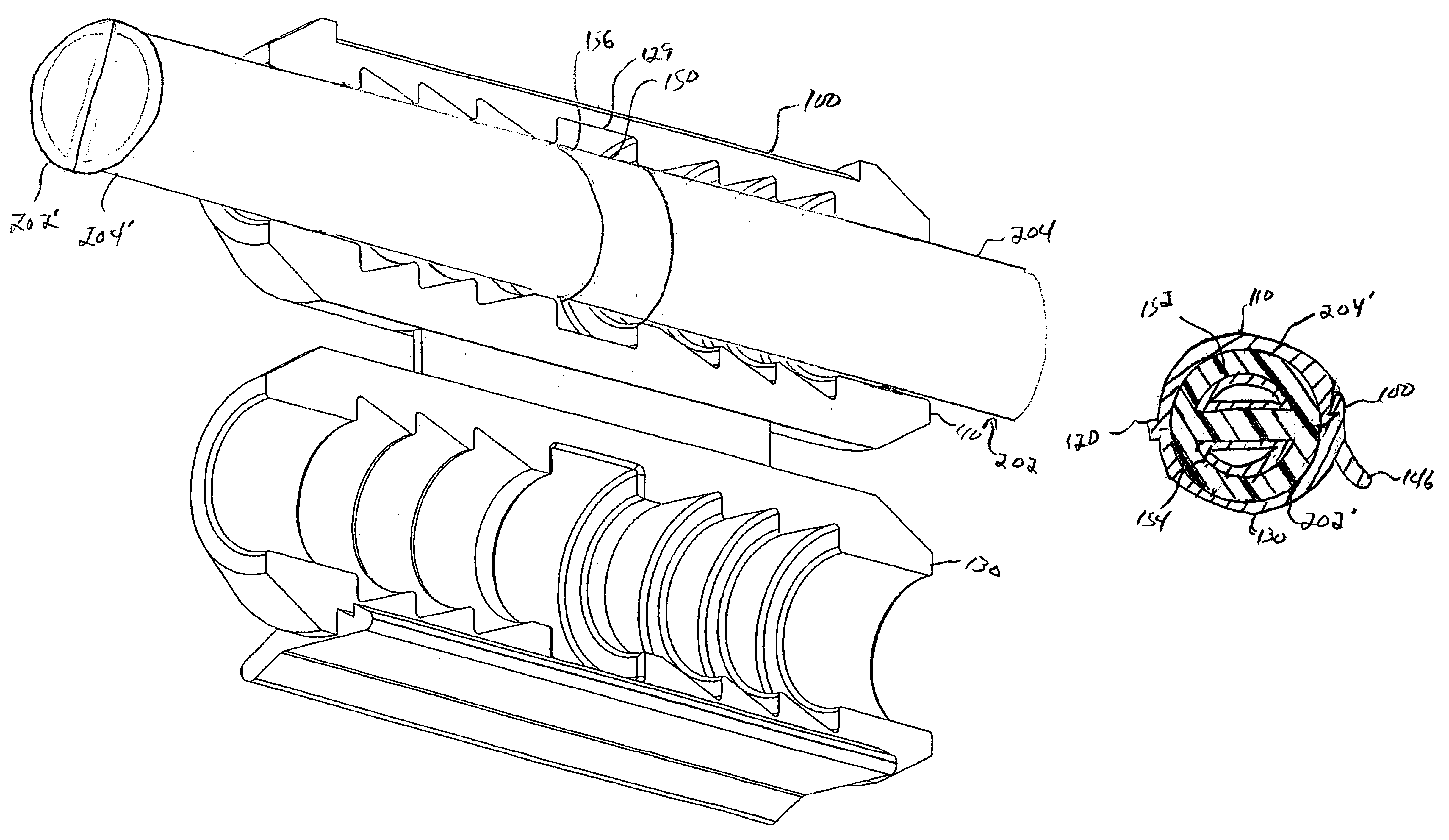
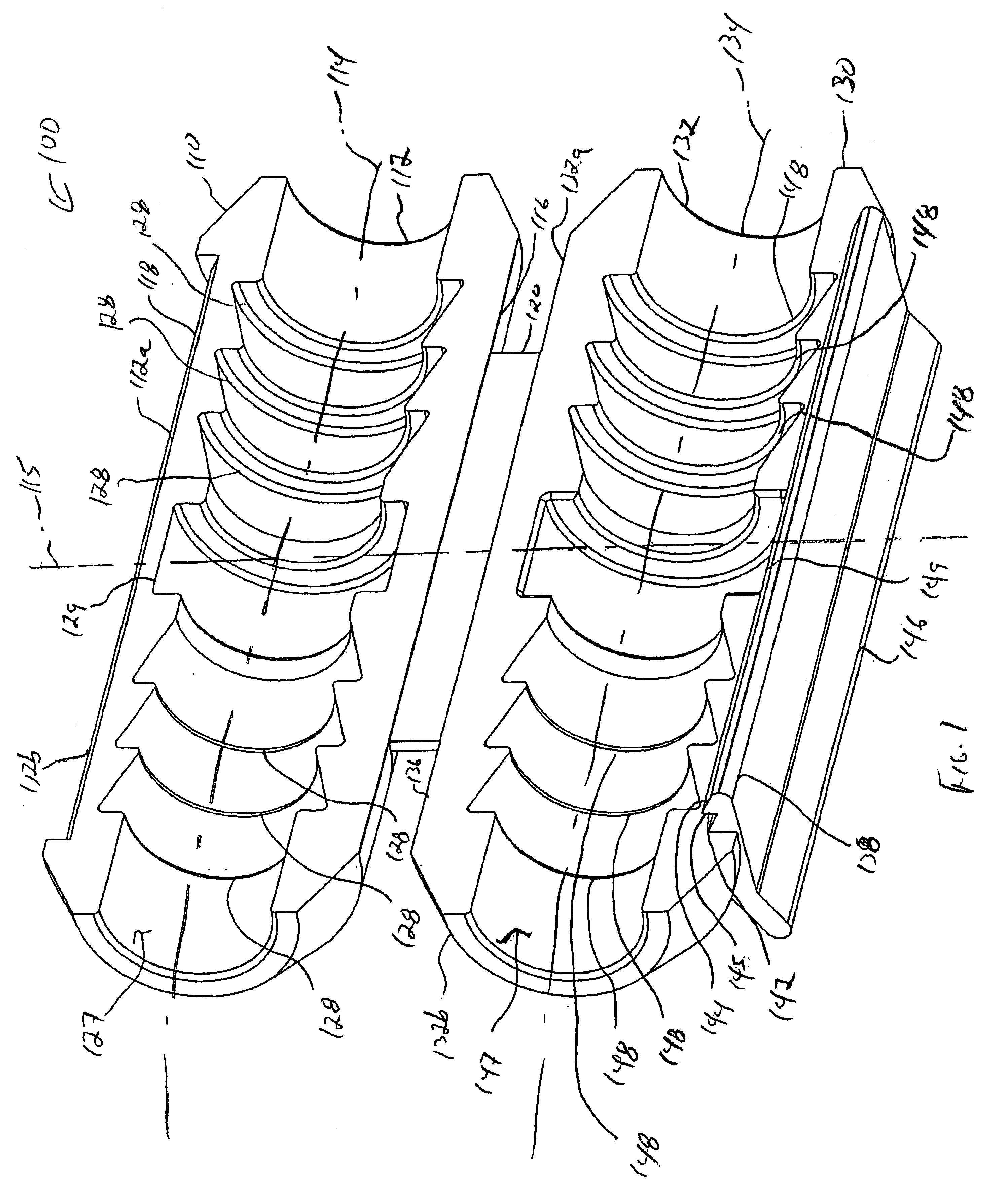
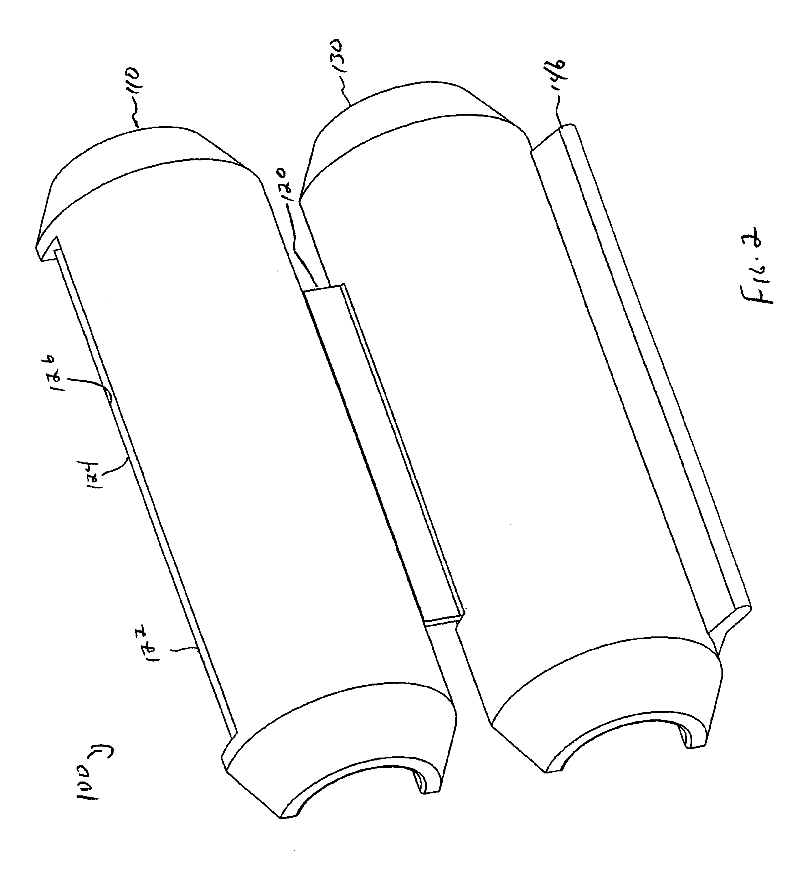
[0022]In the drawings, like numerals indicate like elements throughout. Certain terminology is used herein for convenience only and is not to be taken as a limitation on the present invention. The words “proximal” and “distal” refer to directions away from and closer to, respectively, the insertion tip of a catheter that utilizes the coupler according to the present invention. The terminology includes the words above specifically mentioned, derivatives thereof, and words of similar import. The following describes a preferred embodiment of the invention. However, it should be understood based on this disclosure, that the invention is not limited by the preferred embodiment described herein.

[0023]Referring now to FIGS. 1-3, a catheter repair coupler 100 according to the present invention is shown. The coupler 100 includes a first portion 110 and a second portion 130. The first portion 10 includes a generally elongated semi-tubular first body 112 having a longitudinal axis 114 extendin...


PUM


Abstract

A coupler for a flexible tube is disclosed. The coupler includes a first channeled member having a generally semicircular cross-section and a first longitudinal axis extending therethrough and a second channeled member having a generally semicircular cross-section and a second longitudinal axis extending therethrough. The first longitudinal axis is generally parallel to the second longitudinal axis. A hinge connects a first length of the first channeled member to a first length of the second channeled member. A lateral axis generally bifurcates the first length of the first channeled member and the first length of the second channeled member. A plurality of barbs are disposed in each of the first and second channeled members, wherein each barb extends generally toward an intersection of the longitudinal axis of its respective channeled member and the lateral axis. A lock secures a second length of the first channeled member to a second length of the second channeled member.

Description

CROSS REFERENCE TO RELATED APPLICATION[0001]The present application claims priority from U.S. Provisional Patent Application Ser. No. 60 / 447,115, filed Feb. 13, 2003.FIELD OF THE INVENTION[0002]The present invention relates to a coupler that is used to repair a flexible conduit, such as a catheter.BACKGROUND OF THE INVENTION[0003]Catheters for the introduction or removal of fluids may be located in various venous locations and cavities throughout the body of a patient for introduction of fluids to the body or removal of fluids from the body. Such catheterization may be performed by using a single catheter having multiple lumens. A typical multiple lumen catheter is a dual lumen catheter in which one lumen introduces fluid and the other lumen removes fluid. An example of such a multiple lumen catheter assembly is the SPLIT-CATH® catheter. Catheterization may also be performed by using separate, single lumen catheters inserted through two different incisions into an area to be cathete...

Claims


Application Information

Patent Timeline
IPC IPC(8): A61M39/10A61M39/00F16L31/00F16L39/00F16L21/06A61M25/00
CPCA61M39/1011F16L21/06F16L31/00F16L39/00A61M25/00A61M39/10A61M2039/1027Y10S285/921
Inventor FISHER, MARK
Owner MEDICAL COMPONENTS INC
Features
  • Generate Ideas
  • Intellectual Property
  • Life Sciences
  • Materials
  • Tech Scout
  • Unparalleled Data Quality
  • Higher Quality Content
  • 60% Fewer Hallucinations
Learn More