Removable fin system

a technology of fins and fins, applied in the field of removing fins, can solve problems such as reducing the efficiency of fins

Inactive Publication Date: 2005-07-12
LOW PRESSURE SYST
View PDF38 Cites 24 Cited by
  • Summary
  • Abstract
  • Description
  • Claims
  • Application Information

AI Technical Summary

Problems solved by technology

Whilst this system is acceptable, it has been found that the reverse taper on the wings of the tab, allows the tab to wiggle partway out of the slot in certain conditions of high stress, which greatly reduces the efficiency of the fin.

Method used


Image

  • Removable fin system
  • Removable fin system
  • Removable fin system

Examples


Embodiment Construction

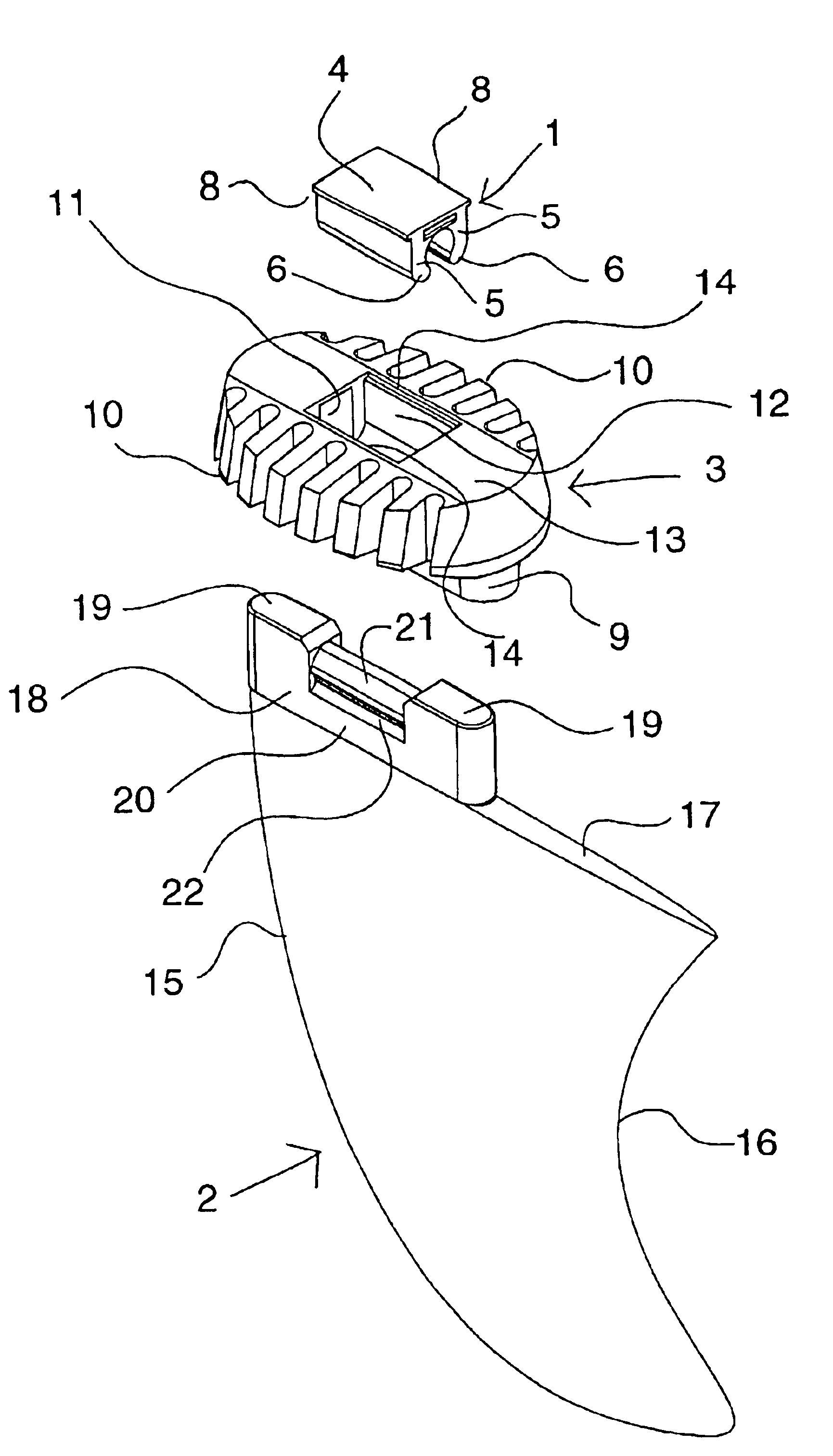
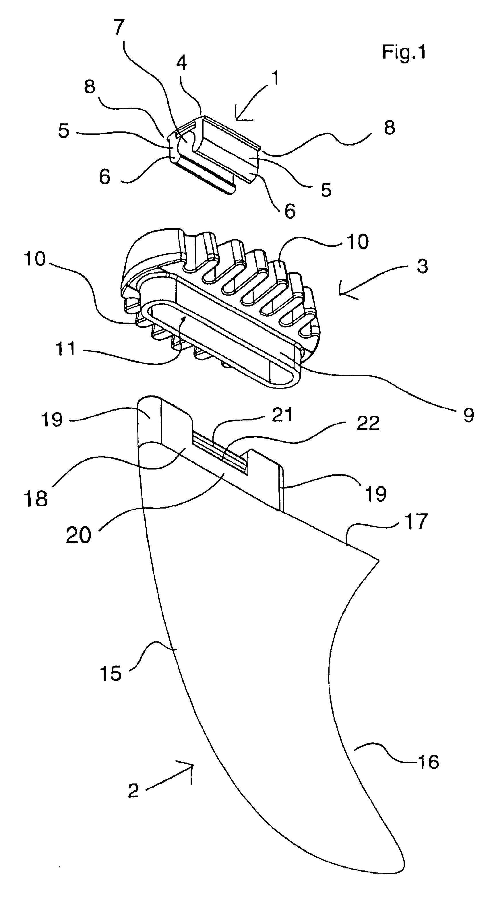
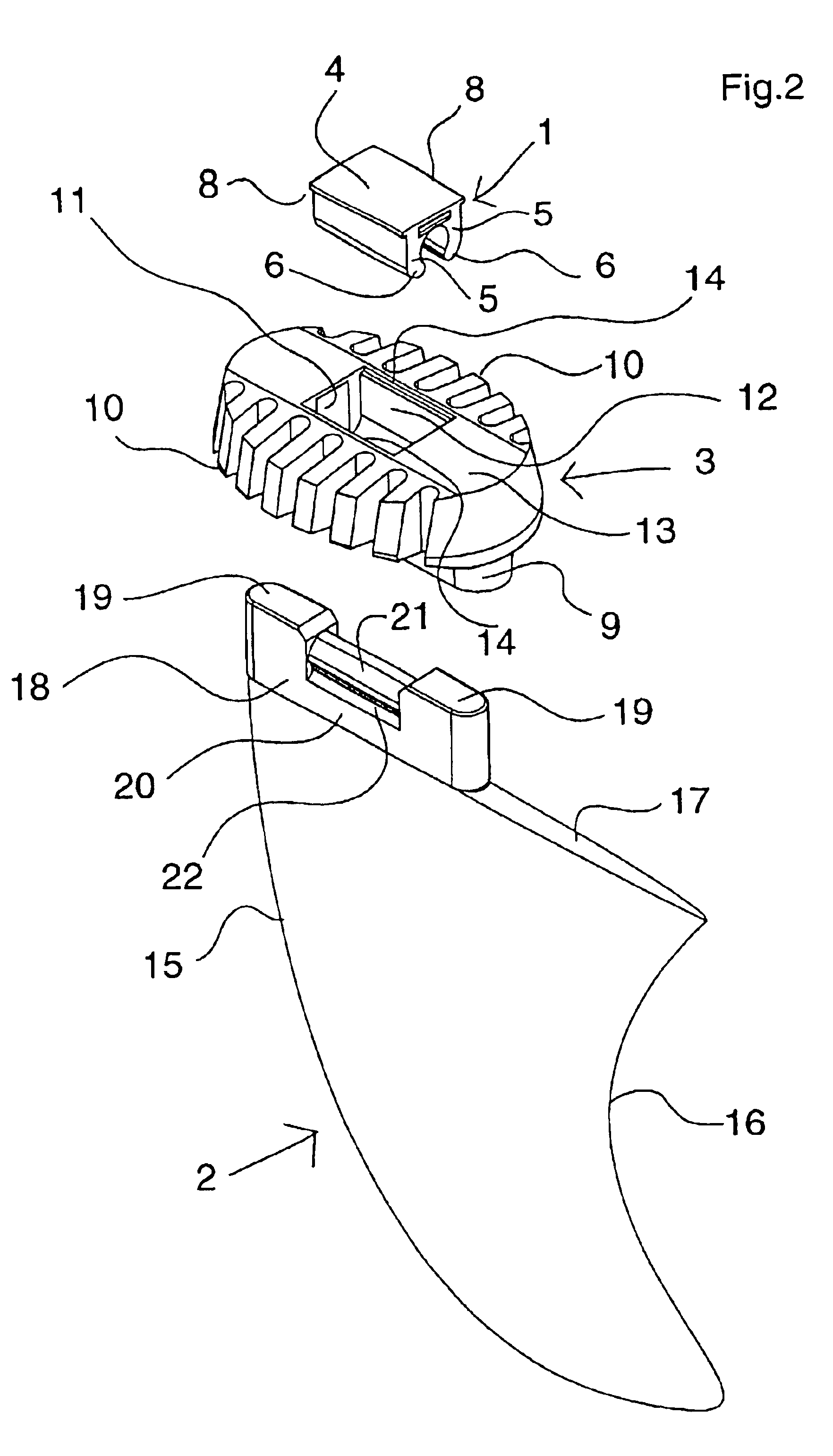
[0038]As shown in FIGS. 1, 2 and 3, a replaceable fin system according to one embodiment of the present invention comprises a clip (1), a fin (2) and a pot (3). The clip (1) comprises a base (4) having two arms (5), terminating in free ends (6), forming a c-shaped cavity (7) therebetween. The clip (1) also has two shoulders (8) extending outwardly from the base (4) beyond the arms (5).

[0039]The pot (3) comprises a central body (9) having an array of outwardly extending wings (10) on each side thereof. A longitudinally extending closed slot (11) extends into the central body (9) and a cutout (12) is formed in the base (13) of the pot (3) to receive the clip (1). Whereby the clip (1) extends into the slot (11) with the shoulders (8) of the clip (1) abutting against the recessed shoulders (14) of the cutout (12).

[0040]The fin (2) comprises a leading edge (15), a trailing edge (16) and a base (17), with a tab (18) extending therefrom. In the described embodiment, the tab (18) starts at ...


PUM


Abstract

A pivotal fin system, for use with an aquafoil, such as surfboards, body boards, wave skis, sail boards, wake boards and the like, comprising a pot (3) and a fin (2), having a tab (18) extending from the base (17) of the fin (2). The pot (3) has a central slot (11) and is mounted in the board (23) with the opening of the central slot (11) flush with the board (23). The slot (11) has a releasable locking means (6 &7) therein, and the tab (18) has a connection means (21 &22), which is releasably engaged by locking means (6 &7). Preferably the releasable locking means (6 &7) is a substantially c-shaped clamp, and the connection means (21 &22) has a recess or recesses (22) behind a bulbous extension (21), which is engaged in the c-shaped clamp, with arms (5) of the c-shaped clamp engaging in the recess or recesses (22).

Description

BACKGROUND OF THE INVENTION[0001]1. Field of the Invention[0002]The present invention relates to a removable fin system, and in particularly to removable fin system for an aquafoil, such as surfboards, body boards, wave skis, sail boards, wake boards and the like.[0003]2. Background and Prior Art[0004]It is known to produce a releasable fin for surfboards and the like, such that the fin can be replaced if damaged, or conditions of the water changes, e.g. different wave conditions. In the prior art, such as Australian patent no. 665804, some of the replaceable fins are affixed to the boards by screws, which requires tools to remove and replace the fin, or by a cam, as in Australian patent 718340. In other situations the replaceable fins have a tab, which fits into a slot cut into the board and has backwardly facing barbed sides, which lock into the core of the board to resist removal.[0005]Another prior art replaceable fin is shown in Australian Patent no. 693962, in which the replac...

Claims


Application Information

Patent Timeline
Patent Type & Authority Patents(United States)
IPC IPC(8): B63B35/73A63B69/00B63B35/79B63B35/81
CPCB63B35/7926B63B35/793B63B32/66
Inventor DAVEY, GRAEMEBANKS, JIMHARPER, DEREK
Owner LOW PRESSURE SYST
Why Eureka
Try Eureka