Method and apparatus for a wire shelf hooking onto slotted brackets

Inactive Publication Date: 2005-07-19
CHICAGO DISPLAY MARKETING
View PDF32 Cites 45 Cited by
  • Summary
  • Abstract
  • Description
  • Claims
  • Application Information

AI Technical Summary

Problems solved by technology

One disadvantage of this rack configuration is that it requires an intermediate bracket to connect the wall-mounted support member to the shelf.
As a result, this rack configuration does not connect the shelf directly to the

Method used


Image

  • Method and apparatus for a wire shelf hooking onto slotted brackets
  • Method and apparatus for a wire shelf hooking onto slotted brackets
  • Method and apparatus for a wire shelf hooking onto slotted brackets

Examples


Embodiment Construction

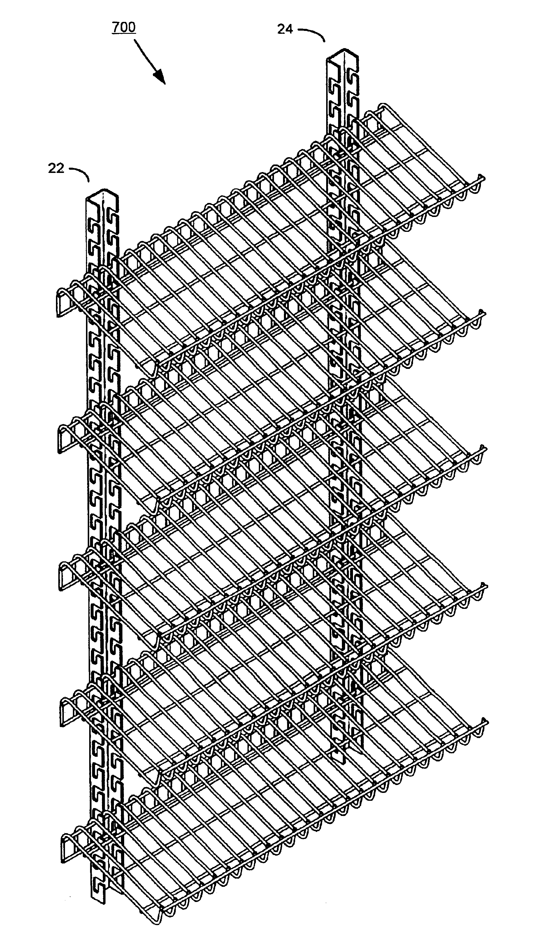
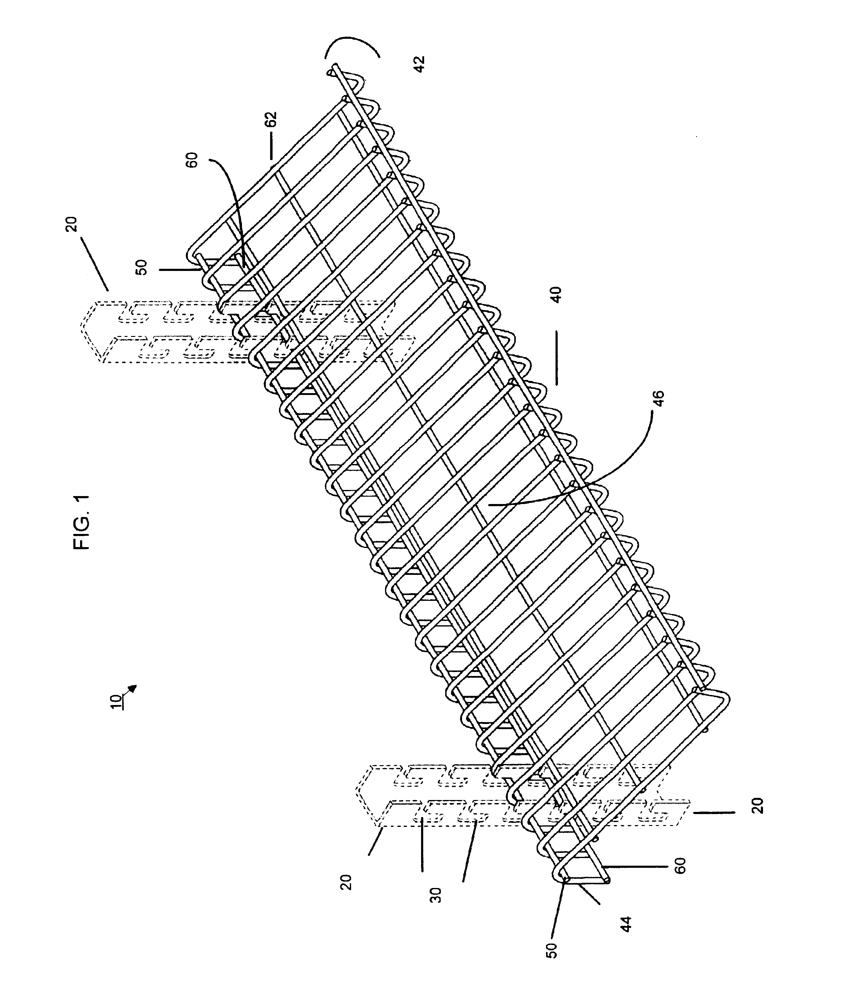
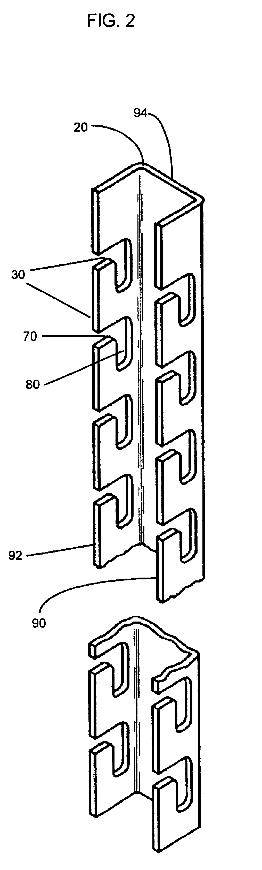
[0016]A rack system including a support having multiple longitudinally spaced slots for connecting at least one generally Z-shaped shelf. The shelf generally has a Z-shape, for example, from a side view. The generally Z-shaped shelf may be composed of, for example, wire or any tubular shaped material constructed from any suitable materials, such as metal, plastic or wood. Additionally, the wire shelf may take on any suitable shape conforming to a generally Z-shaped side view. The shelf has a front leg and a back leg interconnected by a support position. The front leg may, for example, be configured as an upstanding lip having a tubular or flat shape, constructed from wire or sheet metal. The support portion may be a median support portion between the front leg and the back leg of the generally Z-shaped self. The back leg includes a first transverse element disposed adjacent to the support position and a second transverse element disposed at a distal end of the back leg, such that th...


PUM


Abstract

A rack system including a support having multiple longitudinally spaced slots for connecting at least one generally Z-shaped shelf, or any suitable shape. The shelf has a front leg and a back leg interconnected by a support position. The front leg may, for example, provide an upstanding lip. The support portion may be referred to as a median support portion between the front leg and the back leg of the generally Z-shaped shelf. The back leg includes a first transverse element disposed adjacent to the support position, and a second transverse element disposed at a distal end of the back leg, such that the first and second transverse elements engaged adjacent slots in order to connect the shelves to the support. The shelf may be connected to the support having the plurality of longitudinally spaced slots by inserting the generally Z-shaped shelf in order to connect the shelf to the support.

Description

FIELD OF THE INVENTION[0001]The invention relates generally to a rack and, more particularly, to a rack having wire shelves.BACKGROUND OF THE INVENTION[0002]Some rack configurations require the use of an intermediate bracket connected to a wall-mounted support member for supporting a shelf. These intermediate brackets have a vertical front wall with a front face and two side walls each having an inside face. A cantilever arm connects to, and projects generally perpendicular from, the front face and generally away from the two side walls of the intermediate bracket. The wall-mounted support member has a front wall, two parallel side walls generally perpendicular to the front wall and two outer flanges extending from the side walls and generally parallel to the front wall. A connecting assembly permits the intermediate bracket to be connected to the support member. One disadvantage of this rack configuration is that it requires an intermediate bracket to connect the wall-mounted suppo...

Claims


Application Information

Patent Timeline
IPC IPC(8): A47F5/10A47F5/13A47B55/02A47B55/00A47B57/00A47B57/16
CPCA47B55/02A47B57/16A47F5/13
Inventor SPARKOWSKI, ROBERT P.
Owner CHICAGO DISPLAY MARKETING
Why Eureka
Try Eureka