Load-handling system and telescopic arm therefor

a technology of load-handling system and telescopic arm, which is applied in the direction of loading/unloading, lifting devices, storage devices, etc., can solve the problems of large installation space, large space needed, and severe limitations in the capacity of the load-handling system, so as to reduce friction-induced wear and compact structure of few individual parts

Inactive Publication Date: 2005-08-02
TGW MECHANICS GMBH
View PDF15 Cites 162 Cited by
  • Summary
  • Abstract
  • Description
  • Claims
  • Application Information

AI Technical Summary

Problems solved by technology

The primary disadvantage of these systems is that a large amount of space is needed to mount the requisite guide and support rollers for the middle and the handling table and the capacity of the load-handling system is severely restricted.
The disadvantage of all of these systems is that a large amount of installation space is needed for the one endless drive element, e.g. chain, belt, for transmitting a feed motion to the individual slides of the telescopic arms enabling its multiple deflections, with the unavoidable disadvantage that the rack storage capacity can be used to only a low degree because the vertical distance needed to lower the storage unit, e.g. pallet, box, between two rack stages disposed in planes one above the other is considerably increased as a result.

Method used


Image

  • Load-handling system and telescopic arm therefor
  • Load-handling system and telescopic arm therefor
  • Load-handling system and telescopic arm therefor

Examples


Embodiment Construction

[0042]Firstly, it should be pointed out that the same parts described in the different embodiments are denoted by the sa me reference numbers and the same component names and the disclosures made throughout the description can be transposed in terms of meaning to same parts bearing the same reference numbers or same component names. Furthermore, the positions chosen for the purposes of the description, such as top, bottom, side, etc,. relate to the drawing specifically being described and can be transposed in terms of meaning to a new position when another position is being described. Individual features or combinations of features from the different embodiments illustrated and described may also be construed as independent inventive solutions or solutions proposed by the invention in their own right.

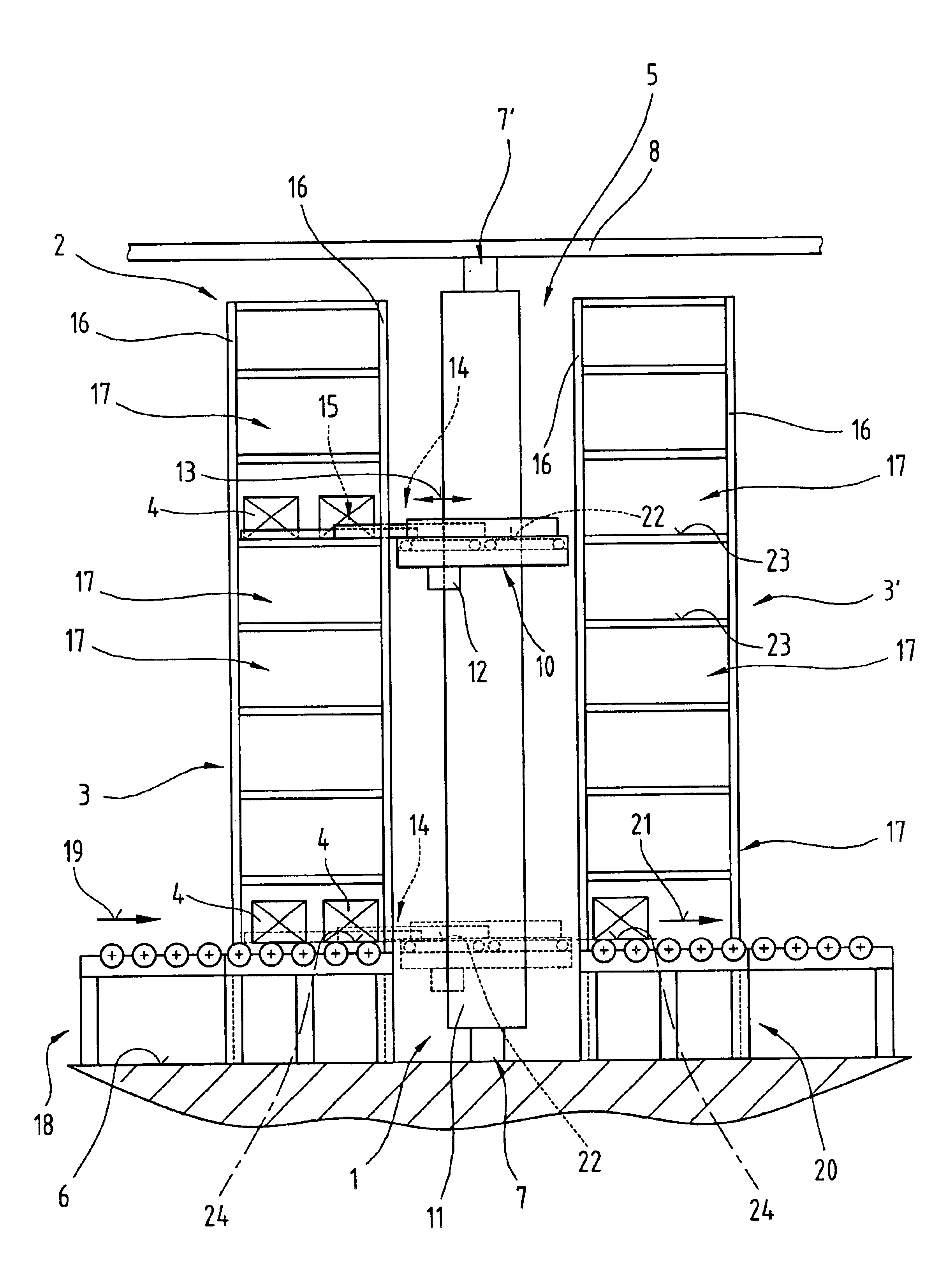
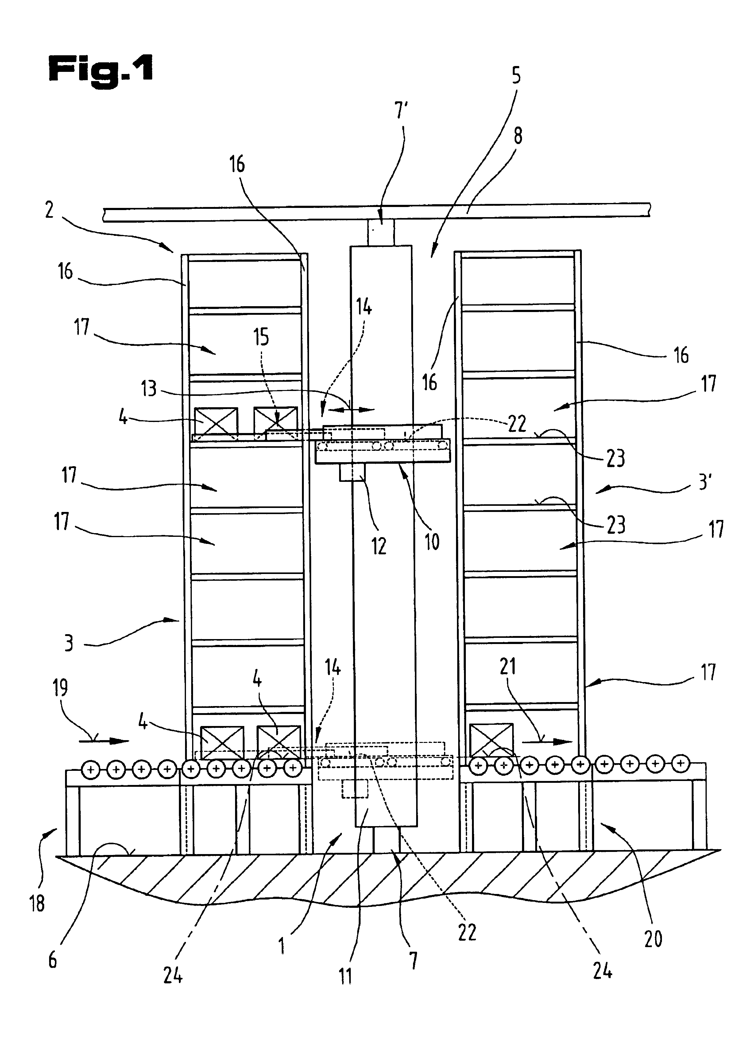
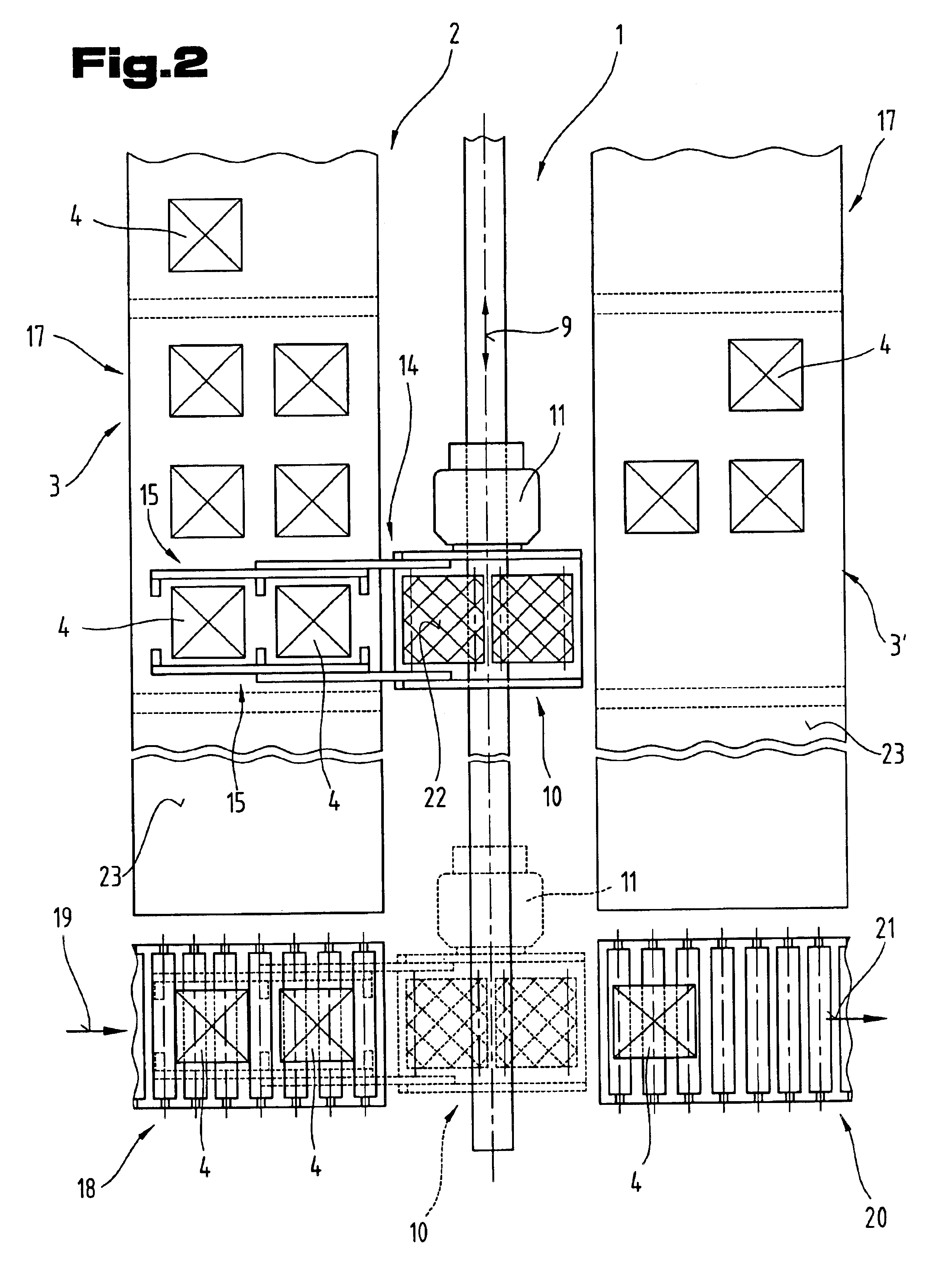
[0043]FIGS. 1 and 2, which will be described together, show a conveyor vehicle, in particular a rack serving unit 1, and a racking system 2, in this example an upright rack system with ...


PUM


Abstract

A telescopic arm of a load-handling system for transferring storage units into and out of a rack stage of a racking system is displaceably supported on a support frame and has a plate-shaped middle slide and a plate shaped top side displaceable relative to the support frame and to each other. The support frame is in the form of a hollow section and has first and second upright longitudinal side walls and a bottom and a top side wall. Lateral guide tracks and a vertical guide track are arranged on the first upright longitudinal side wall. The top slide has lateral guide tracks and a vertical guide track as well as movable drivers for pushing a front or rear face of the storage unit. The middle slide is slidably guided between the support frame and top slide.

Description

TECHNICAL FIELD[0001]The invention relates to a telescopic arm of a load-handling system for transferring storage units into or out of a rack stage of a racking system, which is guided in a respective guide mechanism extending in the longitudinal direction of a support frame with a lateral and vertical guide track, and[0002]a load-handling system for transferring storage units into and out of a rack stage of a racking system with two parallel support frames spaced at a distance apart for synchronously displaceable telescopic arms on a loading platform of a conveyor vehicle, e.g. a rack serving unit, each of which is guided in a guide mechanism extending in the longitudinal direction of the support frame with a lateral and vertical guide track.THE PRIOR ART[0003]A load-handling system is known from patent specifications DE 44 22 240 A1 and U.S. Pat. No. 5,002,449 for transferring containers into and out of a rack stage of a racking system, whereby two telescopic arms arranged on a lo...

Claims


Application Information

Patent Timeline
Patent Type & Authority Patents(United States)
IPC IPC(8): B66F9/07B65G1/04
CPCB65G1/0435B66F9/07
Inventor HANSL, RUDOLF
Owner TGW MECHANICS GMBH
Why Eureka
Try Eureka