Deterrent strip for repelling birds and other pests

a technology of repellent strips and strips, which is applied in the field of strips, can solve the problems of unable to eliminate stretching problems, and the strip flaps up and down, and achieve the effect of resisting lengthwise stretching of strips

Inactive Publication Date: 2005-08-16
HOT FOOT AMERICA
View PDF53 Cites 36 Cited by
  • Summary
  • Abstract
  • Description
  • Claims
  • Application Information

AI Technical Summary

Benefits of technology

[0009]Restraint members are attached to and extend between the inner portions of adjacent wire support members across the spaces defined thereby resisting lengthwise stretching of the strip.

Problems solved by technology

One problem resulting from this prior art approach is that strong winds can cause the strip to flap up and down.
This causes lengthwise stretching of the strip, including the undulating wires, and the end result is that the product either bends upwardly into an arch or in certain circumstances stretches so far that it sags over the edge of the building or other support surface on which it is mounted.
However, even this does not eliminate the stretching problem.

Method used


Image

  • Deterrent strip for repelling birds and other pests
  • Deterrent strip for repelling birds and other pests
  • Deterrent strip for repelling birds and other pests

Examples


Embodiment Construction

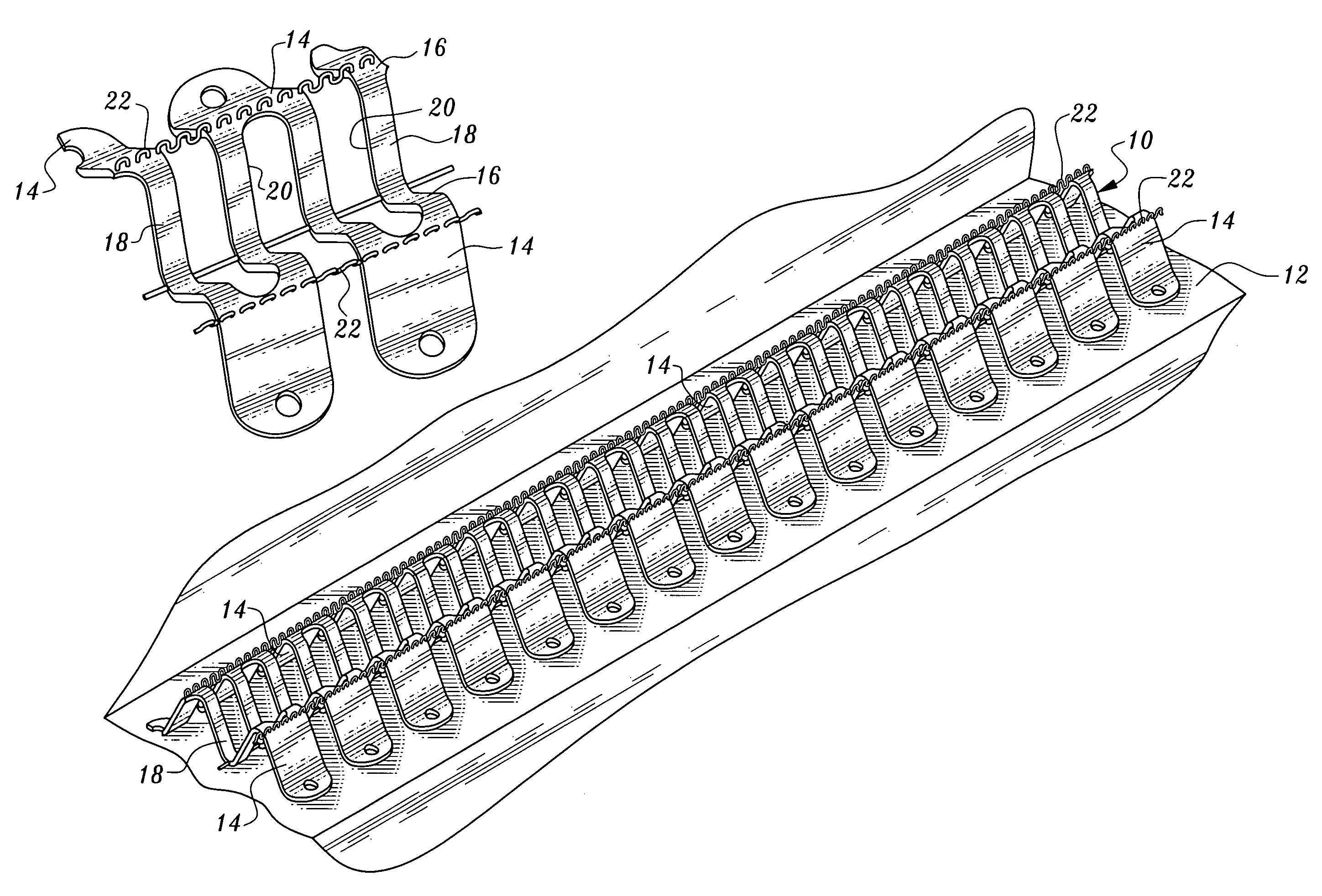
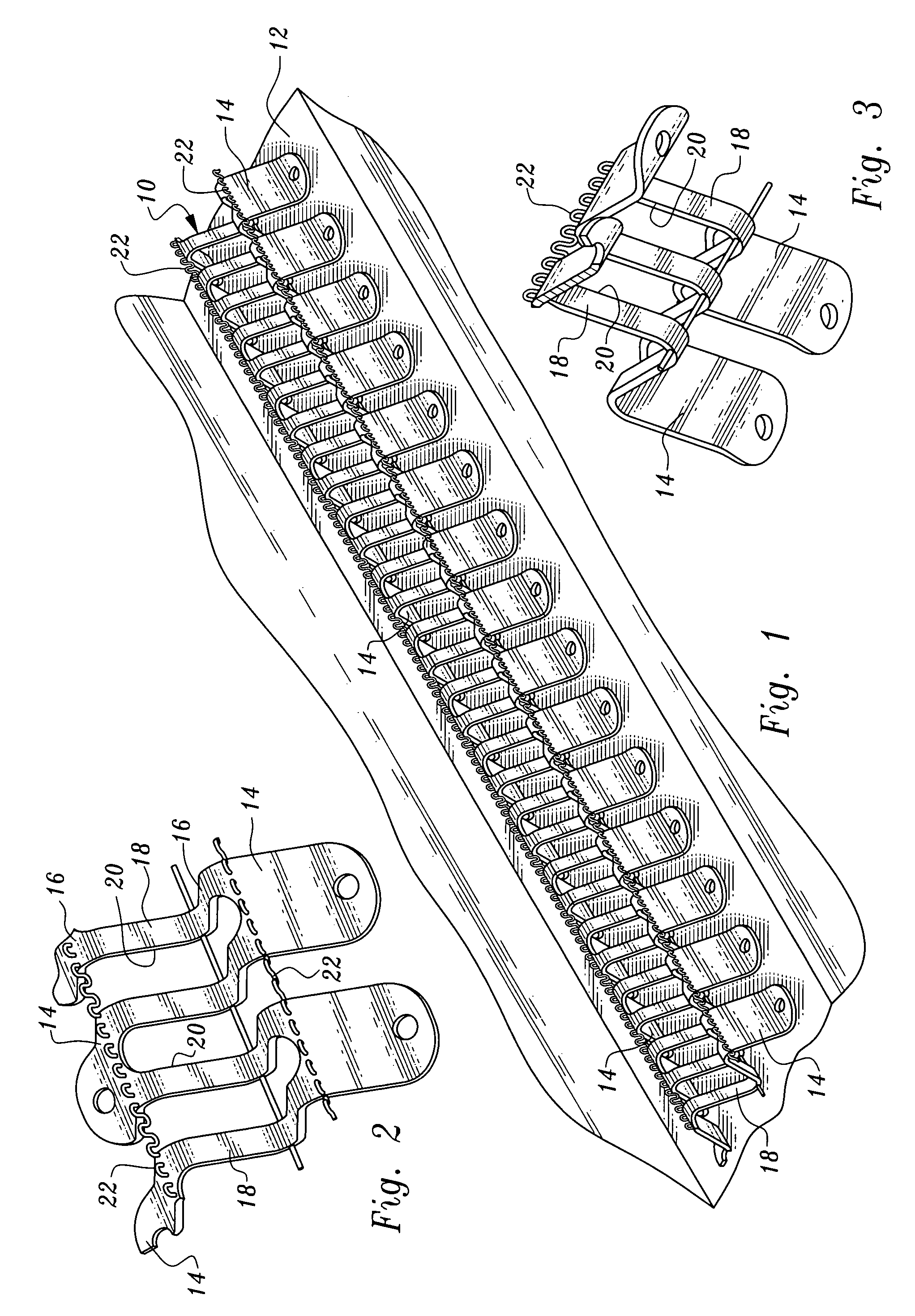
[0020]Referring now to FIGS. 1–7, a strip 10 constructed in accordance with the teachings of the present invention is illustrated. The strip 10 is a deterrent strip for repelling birds and other pests. In FIG. 1, a length of the strip 10 is shown mounted on the ledge 12 of a building, a typical but not exclusive setting for use of the strip.

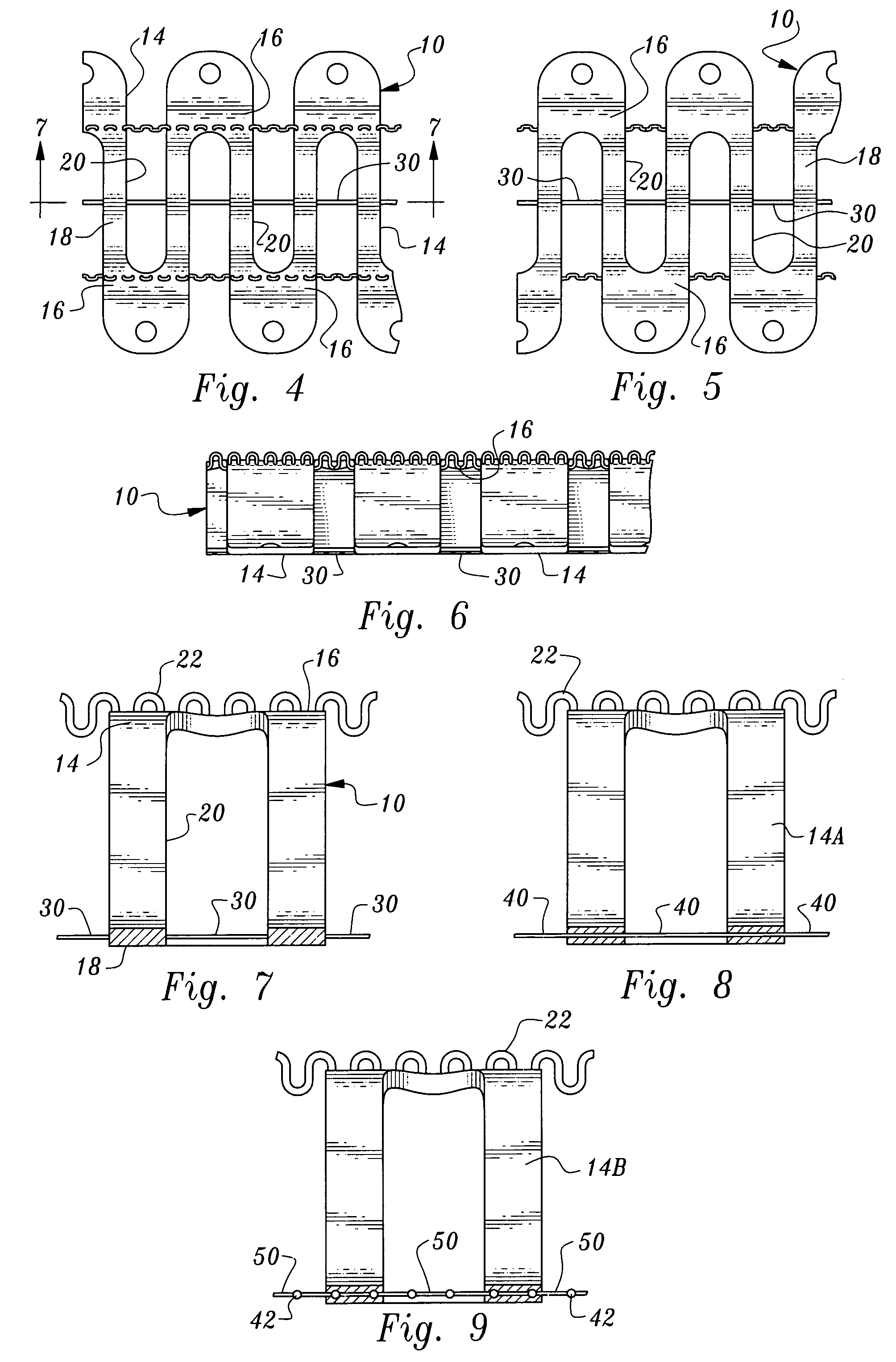
[0021]The strip includes a flexible, bendable base which is comprised of a plurality of wire support members 14 of electrically non-conductive material, for example plastic. Each wire support member includes two spaced wire support portions 16 and an inner portion 18 extending downwardly therefrom. The inner portions of adjacent wire support members define spaces 20 therebetween.

[0022]In the arrangement illustrated, the wire support members 14 are integrally connected. The base comprised of the wire support members has side edges and the spaces 20 defined by the inner portions of the wire support members are in the form of notches extending inwar...


PUM


Abstract

A deterrent strip for repelling birds and other pests includes a non-conductive base supporting two electrically conductive extensible wires. Notches are formed in the base to allow bending. Connectors are attached to wire support members of the base to resist lengthwise stretching of the strip.

Description

TECHNICAL FIELD[0001]This invention relates to a pest repelling device, and more particularly to a strip which may be secured to buildings, statues or other objects to discourage birds and other pests from resting thereon.BACKGROUND OF THE INVENTION[0002]U.S. Pat. No. 6,383,064, issued Sep. 4, 2001, discloses a pest repelling device co-invented by the inventor of the present invention.[0003]The device of U.S. Pat. No. 6,383,064 relates to an elongated deterrent strip for mounting to an inanimate object to discourage birds and other pests from resting on that object. The strip includes a base of electrically non-conductive material. The strip in lateral cross-section has peripheral edges normally lying in a plane and a raised concave center portion. The base has spaced notches along each edge to provide flexibility to the base, whereby the base may be bent both out of the plane and within the plane. The strip further comprises two electrically conductive wires secured to and extendin...

Claims


Application Information

Patent Timeline
Patent Type & Authority Patents(United States)
IPC IPC(8): A01M29/00A01M29/26
CPCA01M29/26
Inventor SNOW, ROGER
Owner HOT FOOT AMERICA
Why Eureka
Try Eureka