Wheelchair wheel lock

a technology for wheelchairs and wheels, which is applied in the direction of hand carts, braking systems, transportation and packaging, etc., can solve the problems of inability to apply additional force, inability and the material strength and resistance of wheelchair parts such as wheelchair locks are finite, so as to prevent inadvertent travel of the chair and increase the weakness in a particular hemisphere

Inactive Publication Date: 2005-08-16
LAWRENCE NELSON
View PDF21 Cites 8 Cited by
  • Summary
  • Abstract
  • Description
  • Claims
  • Application Information

AI Technical Summary

Benefits of technology

[0009]It is known to provide a wheelchair for transporting fully or partially disabled persons, having a frame, a seat and back supported on the frame, and at least two primary drive wheels. When the wheelchair is at rest, it is often desirable to lock the wheels thereof to prevent inadvertent travel of the chair, either with or without an occupant. For example, when a disabled person is exiting or entering the chair, such as to or from a bed, the wheelchair wheels must be locked to provide a secure platform for the user. Accordingly, in one aspect, the present invention provides a wheel locking assembly for substantially preventing rotation of a wheelchair wheel or tire about its axis. Advantageously, the wheel locking assembly of the invention allows the user to lock both wheels of the wheelchair from a single side of the chair, rather than requiring the user to access separate locking mechanisms on opposed sides of the chair as is necessary in conventional wheelchair wheel lock designs. It will be appreciated that this feature provides significant advantages for users having a increased weakness in a particular hemisphere of the body, such as is common for stroke victims.
[0012]Advantageously, the wheel locking assembly of this invention allows the actuating lever to remain operably connected to the first wheel-engaging member regardless of whether the second wheel stop is functional. For example, as will be described in greater detail below, if the continuously flexible linkage operably connecting the first and second wheel-engaging members is severed, the user may continue to lock at least one wheel of the wheelchair to prevent rotation thereof, thereby allowing continued use of the chair.
[0013]Conventional wheelchair wheels include a ground-engaging portion, typically fabricated of a resilient material such as rubber. To be effective for their intended purpose, wheelchair wheel locks must contact this ground-engaging portion with sufficient force to prevent rotation of the wheel or tire. This usually causes the wheel-contacting surface of the wheel-engaging member to partially indent the ground-engaging portion, thereby reducing the likelihood of rotation. However, with conventional wheelchair wheel locks there is still a possibility of slippage.
[0014]To address this problem, the wheel-engaging member of the present invention includes a wheel-contacting surface having a cutout for grippingly engaging the wheel or tire. The wheel-contacting surface of the present invention partially indents the resilient ground-engaging portion of a wheelchair wheel. Additionally, as the wheel-contacting surface is biased against the ground-engaging portion of the wheel with the desired force, a portion of the resilient material of the ground-engaging portion protrudes into the cutout, thereby significantly improving the stopping or gripping force on the wheel compared to a conventional wheel lock. The cutout may be of any dimensions suitable for providing a space into which the wheel ground-engaging surface may protrude. Typically, the wheel-contacting surface cutout is substantially concave.
[0017]In yet another aspect, the present invention provides a wheel locking assembly for substantially preventing rotation of a wheelchair wheel or tire about an axis, comprising a first wheel stop and a second wheel stop for mounting to opposite sides of a wheelchair frame. The first wheel stop may comprise a mounting bracket, a first actuating lever operably connected for displacing a first displaceable wheel-engaging member into or away from contact with a first wheel or tire, and a second actuating lever.
[0019]The second displaceable wheel-engaging member may be operably connected to the second actuating lever by a substantially continuously flexible linkage, which may be a push-pull cable as described above. It will be appreciated that this embodiment of the wheel locking assembly of the present invention allows independent locking control of the two primary drive wheels of a wheelchair, while still preserving the advantageous feature of wheelchair wheels lockable using controls located on a single side of the wheelchair. It will also be appreciated this latter embodiment preserves the feature of being able to lock at least one wheel of the wheelchair even if the continuously flexible linkage is severed.

Problems solved by technology

However, often individuals requiring wheelchairs suffer from greater weakness in one side of the body than the other, such as for example stroke victims.
Because the wheelchair user is often relatively weakened, application of additional force may be difficult.
Further, materials from which wheelchair parts such as wheelchair locks are constructed have a finite strength and resistance to shear forces, and in extreme conditions may break in response to the applied force.

Method used


Image

  • Wheelchair wheel lock
  • Wheelchair wheel lock
  • Wheelchair wheel lock

Examples


Embodiment Construction

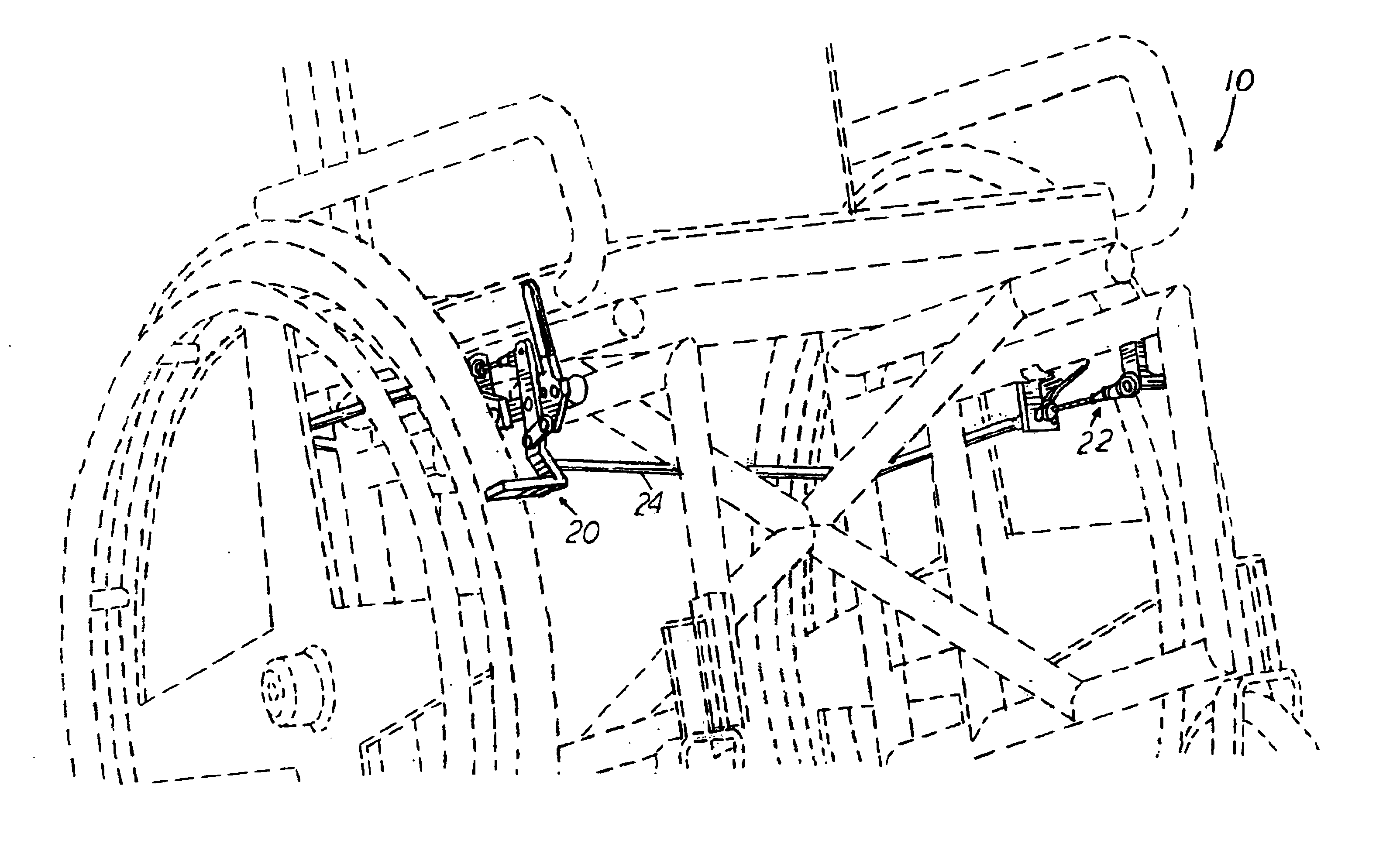
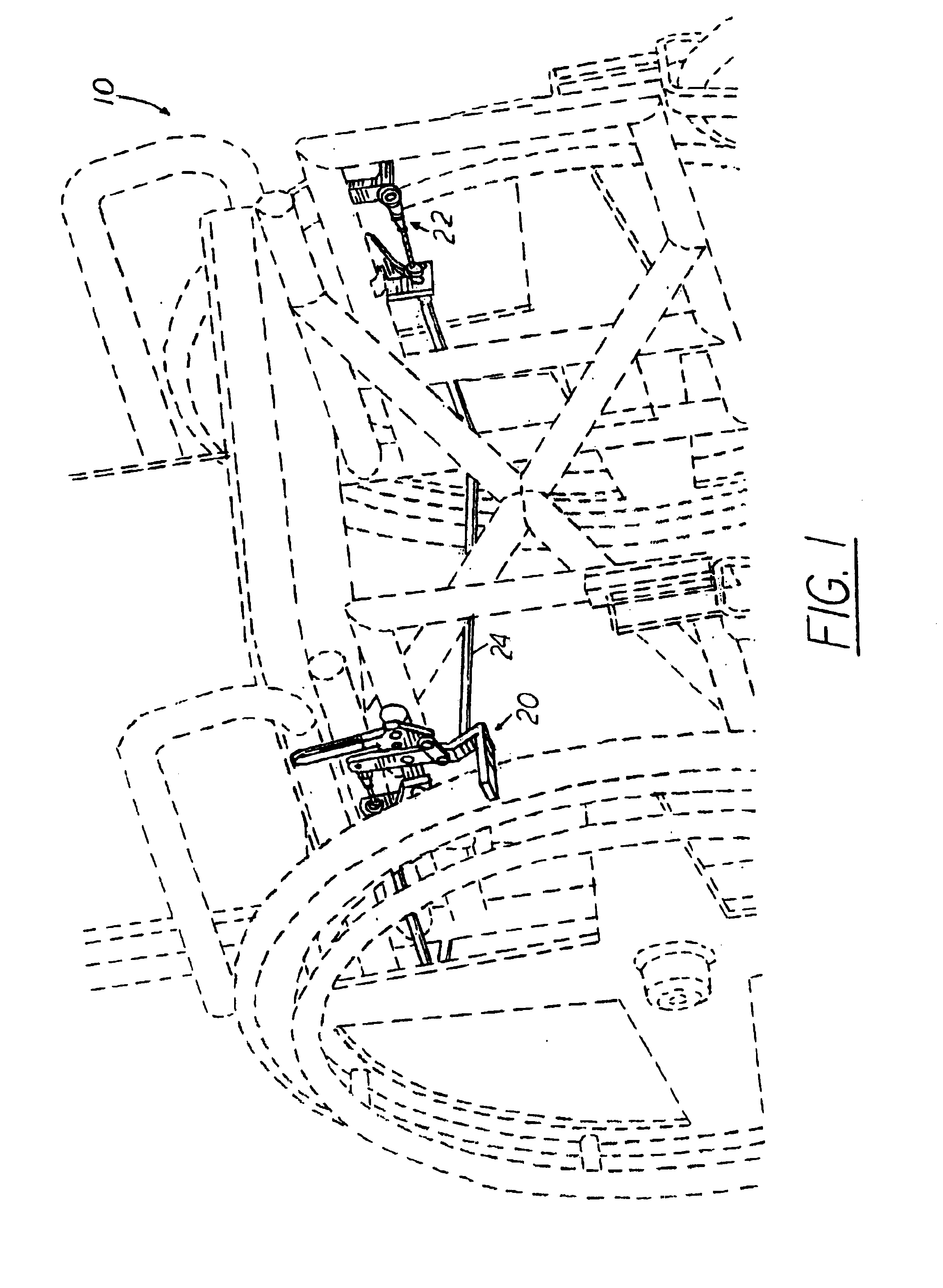
[0027]As best seen in FIG. 1 appended hereto, the wheel locking assembly 10 of the present invention may be mounted to a wheelchair (shown in broken lines for convenience) having a frame, a seat and back attached to the frame, and at least two primary drive wheels. Of course, the wheel locking assembly 10 of this invention will be mounted to the wheelchair such that the wheel locks are in spaced relation to the primary drive wheels to allow locking thereof. The wheel locking assembly 10 of the invention may comprise a first wheel stop 20, a second wheel stop 22, and a substantially continuously flexible linkage 24 operably connecting the wheel stops 20, 22. Wheel stops 20, 22 may be fabricated of any suitably durable, corrosion-resistant material commonly used to fabricate wheelchair wheel stops, including but not limited to metals such as aluminum and stainless steel, and suitably durable plastics or polymers.

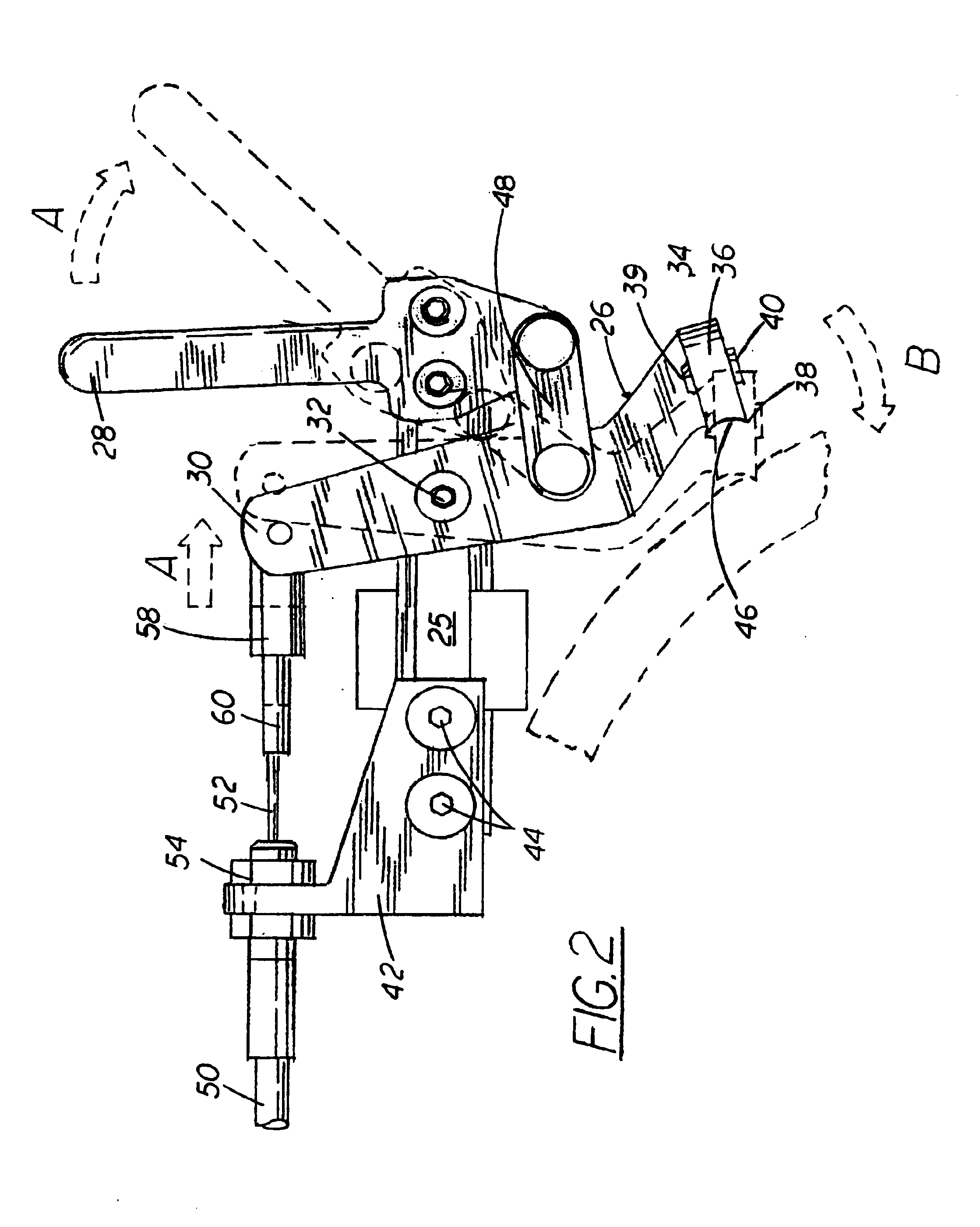
[0028]Referring to FIG. 2, the first wheel stop 20 comprises a mounting b...


PUM


Abstract

A wheelchair wheel locking assembly comprises a first wheel stop having an actuating lever for operating a first wheel-engaging member. The first wheel stop is operably connected to a second wheel stop via a continuously flexible linkage, whereby actuating the first wheel stop simultaneously operates the second wheel stop. In the event the continuously flexible linkage is severed, the first wheel stop may continue to be operated by the actuating lever. The wheel locking assembly of this invention is advantageously operated from a single side of a wheelchair. A wheel locking assembly having dual actuating levers is also provided, whereby from a single side of a wheelchair a first actuating lever operates a first wheel-engaging member and a second actuating lever operates a second wheel-engaging member.

Description

[0001]This application claims the benefit of priority in U.S. Provisional Patent Application Ser. Nos. 60 / 344,612, filed Dec. 26, 2001, and 60 / 409,461, filed Sep. 10, 2002.FIELD OF THE INVENTION[0002]This invention relates generally to the field of wheel locking mechanisms for wheelchairs. In particular, the present invention relates to a wheelchair lock adapted for use by individuals suffering from greater weakness in one hemisphere of the body. The present invention relates further to an improved wheel-contacting surface for a wheel lock, providing enhanced stopping power without necessitating use of additional force.BACKGROUND OF THE INVENTION[0003]It is known to provide wheelchairs with mechanisms for locking the wheels thereof, preventing the wheelchairs from traveling except at the urging of the user. Standard wheelchair locks must be operated from both sides of the chair, that is, the left wheel must be locked from the left side, and the right wheel must be locked from the ri...

Claims


Application Information

Patent Timeline
Patent Type & Authority Patents(United States)
IPC IPC(8): B60T1/04B60T1/00
CPCB60T1/005B60T1/04
Inventor TANKSLEY, KEITH A.DONALDSON, BRUCE S.
Owner LAWRENCE NELSON
Why Eureka
Try Eureka