Valve seal with pressure relief channels and expansion voids

a valve and expansion void technology, applied in the field of valve seals for use with valves, can solve the problems of significant expansion and contraction of the valve seal, fluid which becomes trapped within the cavity,

Inactive Publication Date: 2005-09-06
VICTAULIC
View PDF20 Cites 28 Cited by
  • Summary
  • Abstract
  • Description
  • Claims
  • Application Information

AI Technical Summary

Problems solved by technology

Butterfly valves may be used to control fluids flowing under high pressure and temperature, for example, in excess of 20 atmospheres and above 200° F. Such conditions are very hard on the valve and will cause degradation unless steps are taken to protect the valve components.
Especially troubling are conditions, such as large fluid temperature swings, which cause significant expansion and contraction of the valve seal.
A further problem associated with seal design concerns fluid which becomes trapped within the cavity between the seal and the valve housing.
This presents problems when the valve closes, as the fluid in the cavity is placed under tremendous pressure as the seal is compressed radially outwardly within the cavity against the housing by the closure member.

Method used


Image

  • Valve seal with pressure relief channels and expansion voids
  • Valve seal with pressure relief channels and expansion voids
  • Valve seal with pressure relief channels and expansion voids

Examples


Embodiment Construction

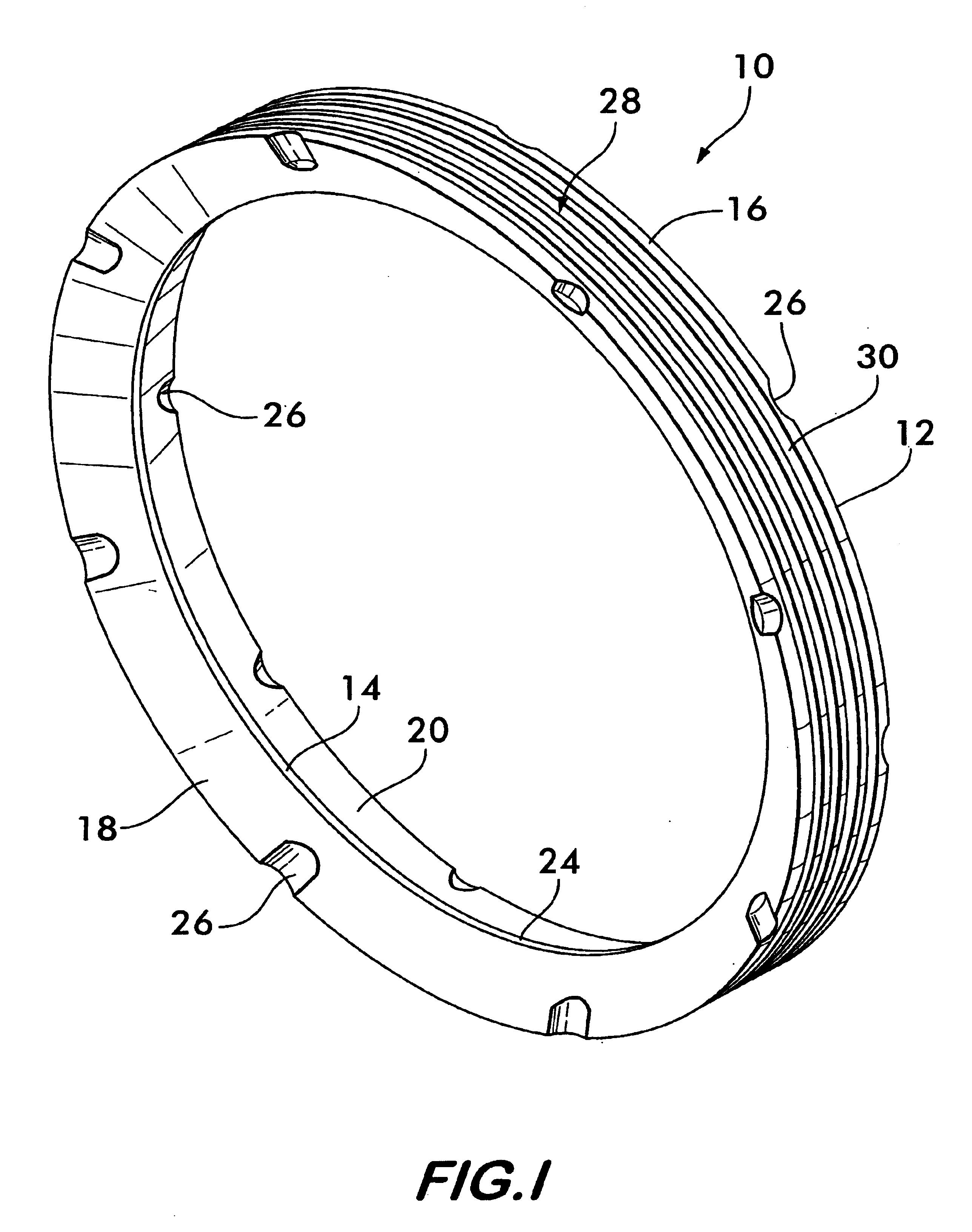
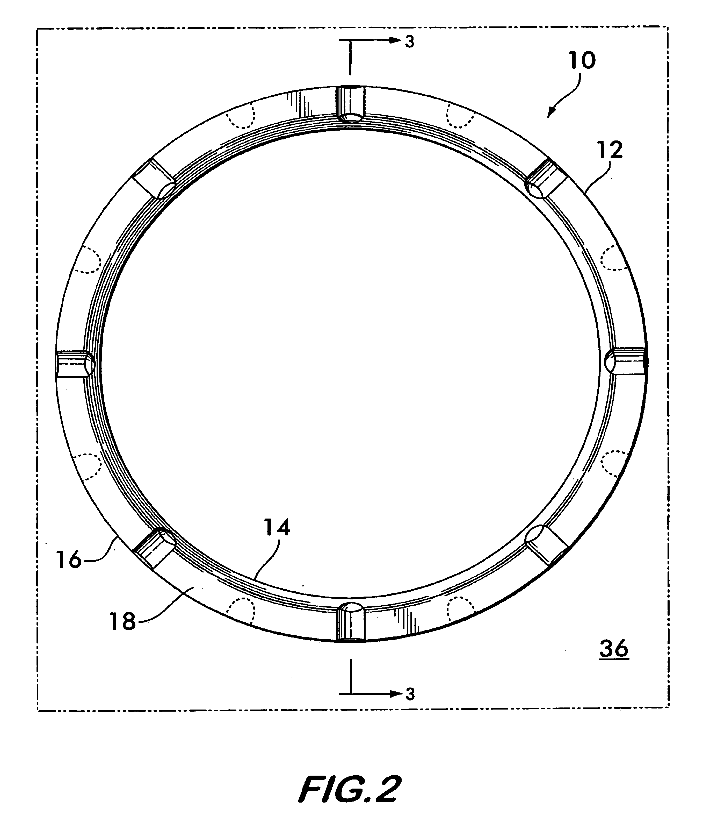
[0022]FIGS. 1 and 2 show one embodiment of a seal 10 according to the invention. Seal 10 comprises a loop 12, preferably circular in shape, although other shapes such as oval, ellipsoidal, polygonal and racetrack shaped are also feasible. Loop 12 is flexible and resilient and may comprise elastomeric compounds, natural rubbers as well as thermoplastics such as urethanes. The loop may be formed by compression molding techniques under heat and pressure in a core and cavity type mold or by injection molding techniques when economically justified by large volume production runs.

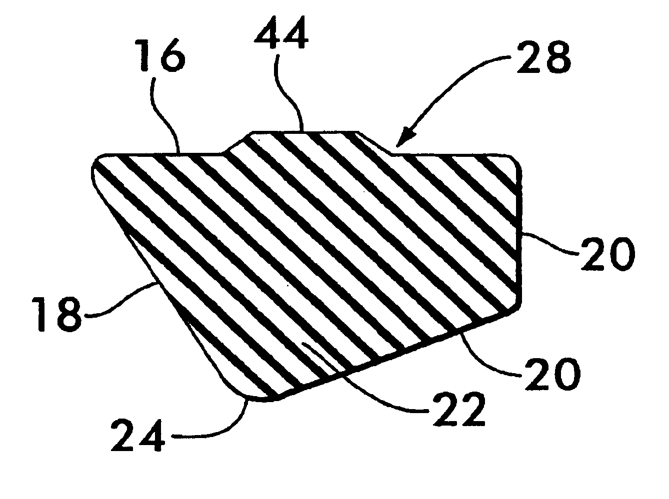
[0023]As best shown in FIGS. 1 and 3, loop 12 has a perimeter sealing surface 14 and a perimeter mounting surface 16 between which extend oppositely disposed axially facing surfaces 18 and 20. Perimeter sealing surface 14 is shown positioned on the inner perimeter of loop 12 facing inwardly of the loop, and perimeter mounting surface 16 is positioned on the outer perimeter of loop 12 and facing outwardly of the l...


PUM


Abstract

A flexible, resilient incompressible seal for a butterfly valve is disclosed formed from a loop having a perimeter mounting surface and a perimeter sealing surface with first and second oppositely disposed axial surfaces extend between the perimeter sealing and mounting surfaces. Channels are positioned in the axial surfaces in spaced relation around the seal. The channels extend from the perimeter mounting surface toward the perimeter sealing surface and provide fluid communication to the perimeter mounting surface allowing fluid trapped against the perimeter mounting surface to escape when compressed by the closing of the valve. A void space is positioned in the perimeter mounting surface in the form of grooves or dimples allowing the perimeter sealing surface to deform under compression when the seal is captured within the valve and substantially restrained from deforming.

Description

FIELD OF THE INVENTION[0001]This invention relates to seals for use with valves and especially to seals adapted for use with butterfly valves.BACKGROUND OF THE INVENTION[0002]Valves, such as butterfly valves, having valve closing members rotatably mounted within a housing to effect opening and closing of the valve, are in widespread use throughout a wide spectrum of industrial and commercial activities including the chemical and petroleum industries, the papermaking industry, municipal and industrial water service and in commercial and residential fire suppression systems to cite a few examples.[0003]Butterfly valves and the like often have a flexible, resilient seal mounted within the valve housing and surrounding the closure member. The seal provides a compliant, deformable interface between the valve closing member and the valve housing which effects a fluid tight seal when the closure member is rotated from the open to the closed position to compressively engage the seal.[0004]B...

Claims


Application Information

Patent Timeline
Patent Type & Authority Patents(United States)
IPC IPC(8): F16J15/16F16K1/226
CPCF16J15/164F16K1/2261F16K1/2263F16K27/0218
Inventor BANCROFT, PHILIP W.WESTON, RICHARD R.WORTMANN, STEVEN A.
Owner VICTAULIC
Why Eureka
Try Eureka