Hinge key switch

Inactive Publication Date: 2005-09-06
LITE ON SINGAPORE PTE LTD
View PDF17 Cites 90 Cited by
  • Summary
  • Abstract
  • Description
  • Claims
  • Application Information

AI Technical Summary

Benefits of technology

[0008]Accordingly, the present invention is directed to a hinged key switch having a construction in wh

Problems solved by technology

Also, because there are many interacting and moving parts, the plunger-type key switch is subject to breakage.

Method used


Image

  • Hinge key switch
  • Hinge key switch
  • Hinge key switch

Examples


Embodiment Construction

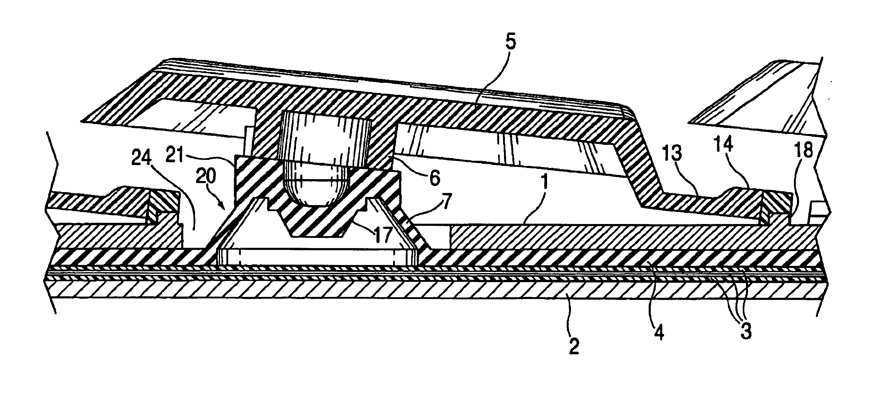
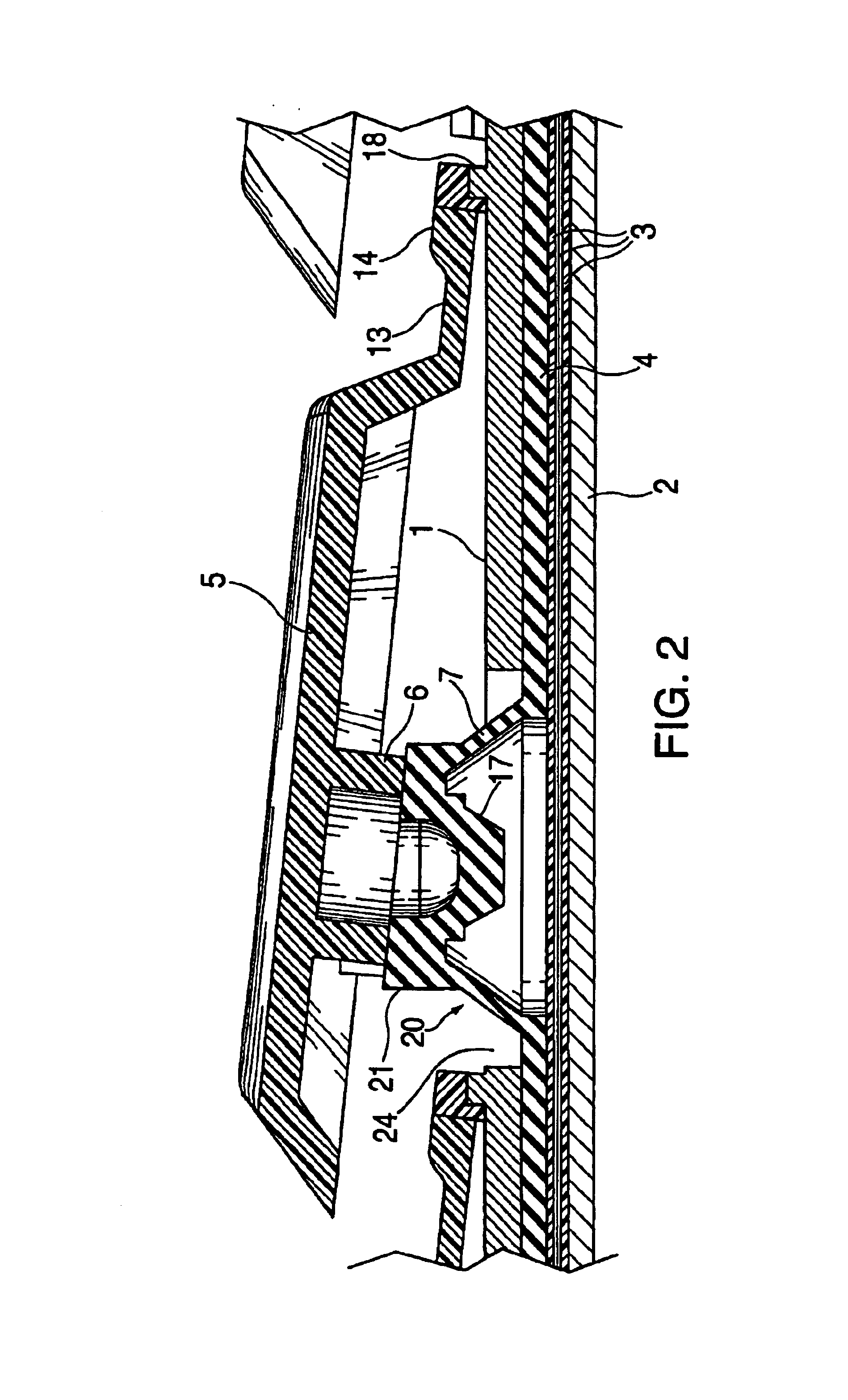
[0020]FIGS. 1 through 6 illustrate an apparatus for construction of a hinged key switch, in which a rubber spring acts as a biasing mechanism to bias a key cap in a vertical direction and in which movement of the key cap is controlled by a horizontal pivot point outside of the axis of vertical movement.

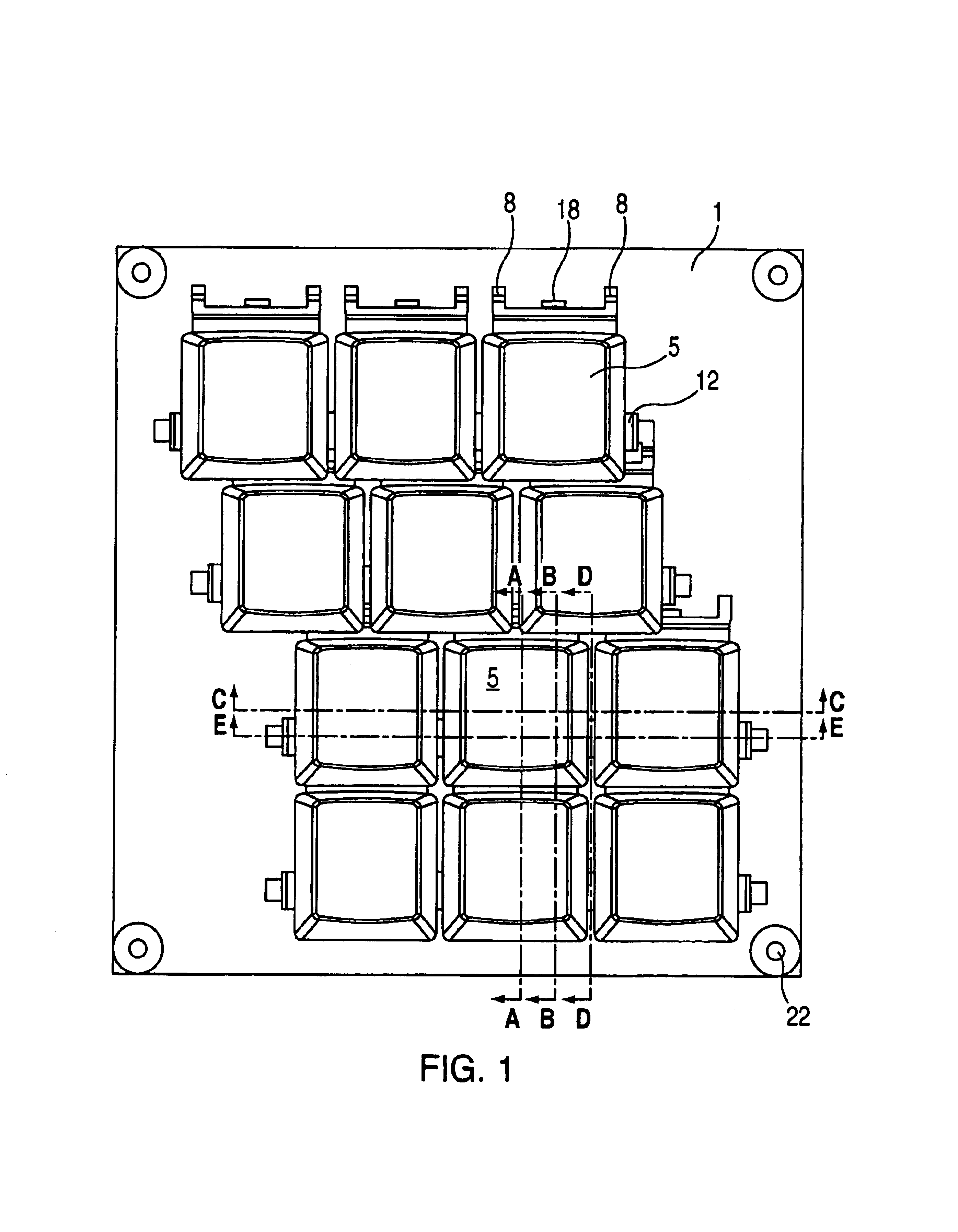
[0021]Referring now to FIG. 1, a keyboard mounting plate 1 is shown with a number of key caps 5 mounted thereon around pivot points 8. As can be seen from the figure, the rows of key caps can be mounted in either a structured column scheme or in a staggered column scheme. Mounting of the key caps in a structured scheme is shown in the figure by the bottom two rows, while the staggered scheme is shown by the top two rows. It is to be understood, of course, that the figure is merely illustrative and that other schemes of mounting of the key caps may be used. To assist in the process of mounting the key caps to the mounting plate, a raised stopper ridge 18 may be added on the surface of ...


PUM


Abstract

An apparatus for a hinged key switch is presented which operates around a hinged pivot point located external to the four points of the key cap, and which comprises a rubber spring providing a vertical bias and an arm with an extension which acts as a stopper when it abuts a raised portion of the mounting plate. The rubber spring is integrally formed from a rubber sheet which is supported on one side by the mounting plate and on the other by the back plate. The stopper extends vertically downward from the key cap and acts to limit the movement of the key in the vertical direction. A horizontal extension from a lower portion of the key cap further extends downward and through a slot in the mounting plate and has a hook which abuts an underside of the mounting plate, such extension from the key cap acting as the pivot point around which the key rotates.

Description

BACKGROUND OF THE INVENTION[0001]The present invention relates to an apparatus for a hinge key switch, and more particularly to a construction of a key switch having a rubber spring which provides vertical resistance against a key cap, movement of which operates around a hinge point, and a stopper which acts to limit that movement.DESCRIPTION OF THE RELATED ART[0002]Information is input into electronic devices, such as computers and other types of data terminals, by means of a keyboard. Accordingly, the construction of the key switches of the keyboard becomes important in that the key switches must be durable and be able to be manually depressed in a consistent and easy manner. Two alternative methods of construction of these key switches have heretofore been contemplated. These two types of switches are commonly known as the “plunger-type” key switch and the “scissors-type” key switch.[0003]Referring first to FIG. 7, a plunger-type key switch is illustrated according to the prior a...

Claims


Application Information

Patent Timeline
IPC IPC(8): H01H13/70H01H13/705
CPCH01H13/705H01H2215/006H01H2221/016
Inventor TAKEDA, TOSHISADAACOSTA, RICHARDFAUBLE, CHARLESSITALASAI, CHATREE
Owner LITE ON SINGAPORE PTE LTD
Why Eureka
Try Eureka