Method and apparatus for controlling minimum brightness of a fluorescent lamp

a fluorescent lamp and minimum brightness technology, applied in the direction of electric variable regulation, process and machine control, instruments, etc., can solve the problems of flickering or shimmering, effective limitation of the dimming range of the ccfl, and limited power required to generate ligh

Inactive Publication Date: 2005-09-20
BANK OF AMERICA N A
View PDF44 Cites 50 Cited by
  • Summary
  • Abstract
  • Description
  • Claims
  • Application Information

AI Technical Summary

Benefits of technology

[0017]The minimum pulse generator circuit includes a differential amplifier, a counter, and a comparator. The differential amplifier produces a pulse when a voltage representative of the current flowing through the CCFL transitions from below a reference voltage to above the reference voltage. The pulse advances a count in the counter. The current value of the count and the control value are compared by the comparator.

Problems solved by technology

Fluorescent lamps are used in a number of applications where light is required but the power required to generate light is limited.
However, lamp characteristics, LCD mechanical structure, operating temperature and s

Method used


Image

  • Method and apparatus for controlling minimum brightness of a fluorescent lamp
  • Method and apparatus for controlling minimum brightness of a fluorescent lamp
  • Method and apparatus for controlling minimum brightness of a fluorescent lamp

Examples


Embodiment Construction

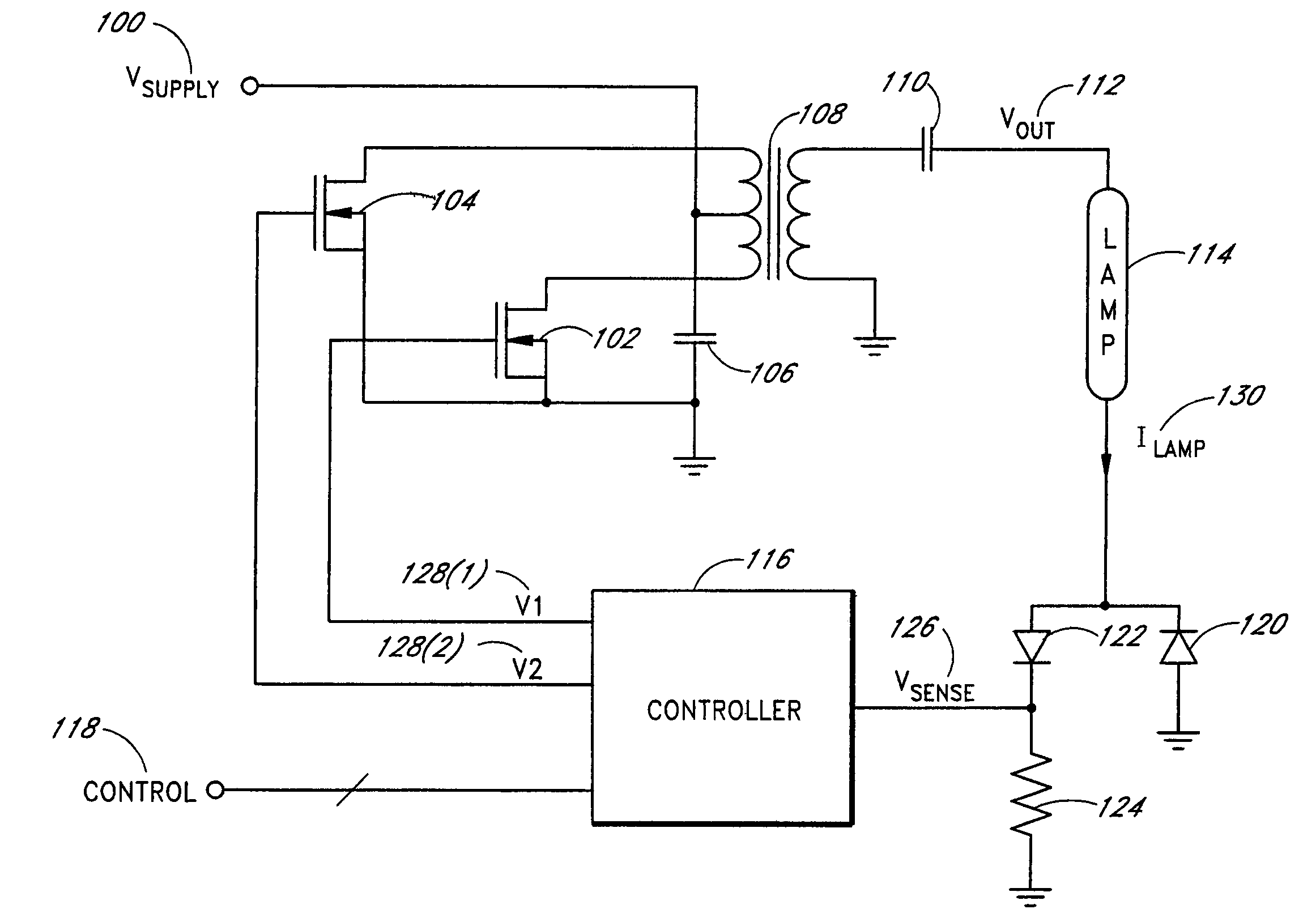
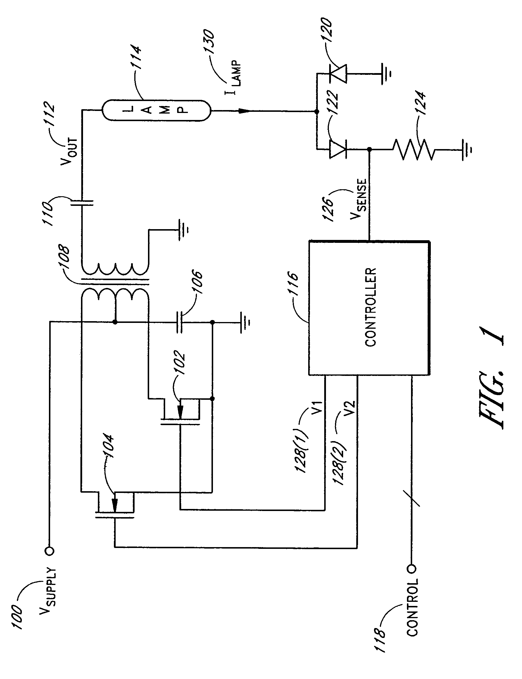
[0024]FIG. 1 is a schematic diagram of a power conversion circuit according to one embodiment of the present invention. The power conversion circuit converts a DC supply voltage (VSUPPLY) 100 into a substantially sinusoidal output voltage (VOUT) 112 to drive a cold cathode fluorescent lamp (CCFL) 114. The supply voltage 100 is provided to a center tap of the primary winding of a transformer 108. An input capacitor 106 is coupled between the supply voltage 100 and ground. The drain terminals of respective field-effect-transistors (FETs) 102, 104 are coupled to respective opposite terminals of the center-tapped primary winding of the transformer 108. The source terminals of the FETs 102, 104 are connected to ground. One of the output terminals of the secondary winding of the transformer 108 is connected to ground while the other output terminal is provided to the first terminal of a capacitor 110. The second terminal of the capacitor 110 is coupled to the input of the CCFL 114.

[0025]A...


PUM


Abstract

An efficient power conversion circuit for driving a fluorescent lamp uses a minimum pulse generator circuit to control the minimum on-time of a time modulated signal to increase the dimming range of the fluorescent lamp operating over a wide range of temperature and supply voltage. A minimum number of lamp current cycles with respective amplitudes above a preset threshold is typically required to avoid flickering or shimmering during minimum brightness. The minimum pulse generator circuit counts the lamp current cycles and adjusts the on-time accordingly to guarantee the minimum number of cycles with respective amplitudes above a preset threshold under all operating conditions.

Description

RELATED APPLICATIONS[0001]This application is a continuation of U.S. application Ser. No. 10 / 234,653 filed on Sep. 3, 2002, now U.S. Pat. No. 6,654,268, which is a continuation of U.S. application Ser. No. 09 / 946,856 filed on Sep. 4, 2001, now U.S. Pat. No. 6,469,922, which is a continuation of U.S. application Ser. No. 09 / 599,625 filed on Jun. 22, 2000, now U.S. Pat. No. 6,307,765, the entire contents of which are incorporated herein by reference.BACKGROUND OF THE INVENTION[0002]1. Field of the Invention[0003]This present invention relates to a power conversion circuit for driving fluorescent lamps, and, more particularly, relates to circuitry in the power conversion circuit which controls the minimum brightness of the fluorescent lamps.[0004]2. Description of the Related Art[0005]Fluorescent lamps are used in a number of applications where light is required but the power required to generate light is limited. One particular type of fluorescent lamp is a cold cathode fluorescent la...

Claims


Application Information

Patent Timeline
IPC IPC(8): H05B37/02H05B41/392
CPCH05B41/3927Y10S315/04
Inventor CHOI, HWANGSOO
Owner BANK OF AMERICA N A
Why Eureka
Try Eureka