
Distributed label switching router

a label switching and router technology, applied in the field of data communication networks, can solve problems such as the ability of packets to easily traverse networks

Inactive Publication Date: 2005-09-20
RPX CLEARINGHOUSE
View PDF9 Cites 36 Cited by
  • Summary
  • Abstract
  • Description
  • Claims
  • Application Information

AI Technical Summary

Benefits of technology

The invention relates to securing data transmission over networks by establishing tunnels through which data can pass without being exposed or detected. In particular, the technical effect of the invention involves creating two layers of security within virtual private networks (VPNs) connected via a non-MPLS network. By doing so, sensitive data transmitted between different locations on the network cannot be easily intercepted or analyzed. Additionally, the invention also includes optimizing the process of waiting for acknowledgements from devices at both ends of a connection, reducing delays and improving overall efficiency.

Problems solved by technology

The technical problem addressed in this patent is how to enable devices called label-switching routers (LSRs) in a network to efficiently forward data packets without requiring them to have detailed knowledge about the contents of their headers.

Method used


Image

  • Distributed label switching router
  • Distributed label switching router
  • Distributed label switching router

Examples


Embodiment Construction

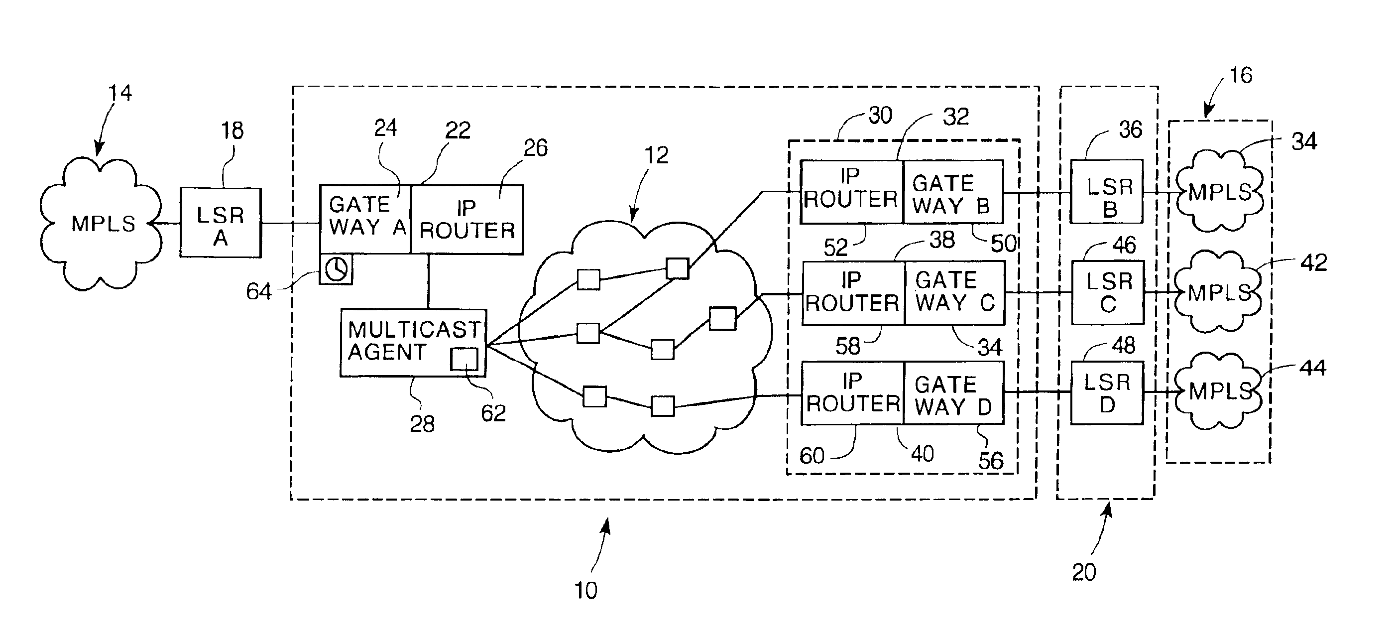
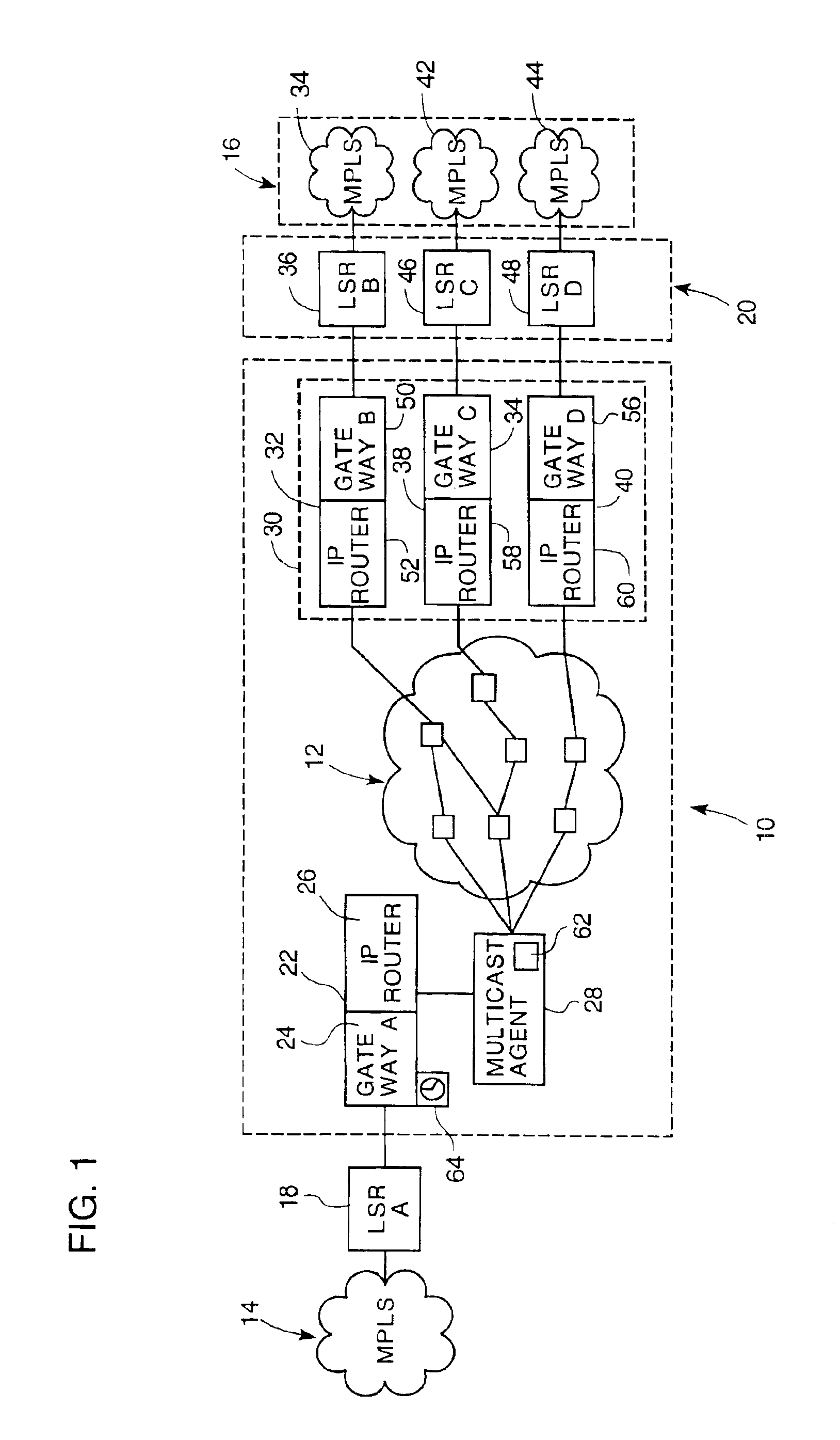
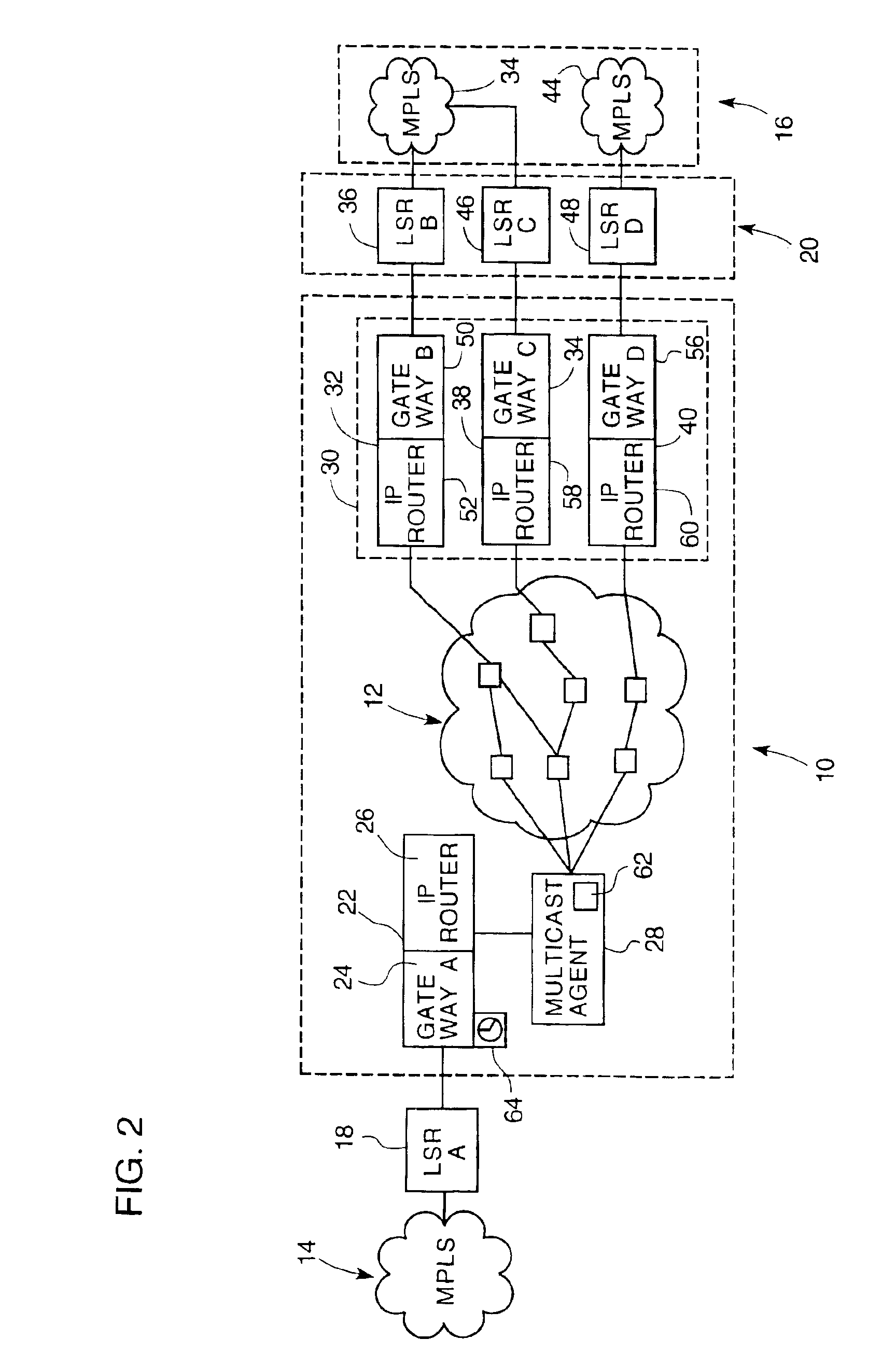
[0024]Referring to FIG. 1, a distributed label-switching router (LSR) 10 interfaces a non-MPLS network 12 with both an input MPLS network 14 and with a plurality of output MPLS networks 16. In the illustrated embodiment, the input MPLS network 14 and the plurality of output MPLS networks 16 form two parts of a virtual private network (VPN). In the context of this description, the non-MPLS network is an IP network 12, however other packet switching networks can be substituted for the IP network 12.

[0025]The IP network 12 is a public network that links these two parts of the VPN. To maintain security of the VPN, data preferably travels along a secure path when traversing the IP network 12. This is achieved by establishing a tunnel across the IP network 12. The distributed LSR 10 dynamically establishes such tunnels on an as-needed basis.

[0026]The input MPLS network 14 connects to the distributed LSR 10 through an input edge LSR 18. Similarly, the output MPLS networks 16 connect to the...


PUM


Abstract

A distributed LSR sends data from a first edge LSR, across a non-MPLS network, to a second edge LSR, thereby enabling a non-MPLS network to interface transparently with MPLS networks. This enables a VPN to use a public network to communicate from one portion of the network to another, remote portion. The distributed LSR includes an ingress gateway logically positioned between the first edge LSR and the non-MPLS network. This ingress gateway receives label requests from the first edge LSR. These label requests are multicast to several egress gateways. At least one egress gateway sends a message back indicating that it can transmit data to the destination. In response, the ingress gateway designates that egress gateway to be a designated gateway. The egress gateway then establishes a tunnel through the non-MPLS network to the ingress gateway.

Description


Claims


Application Information

Patent Timeline
Owner RPX CLEARINGHOUSE
Learn More