Folding multipurpose pocket tool with floating springs

a multi-purpose, spring-type technology, applied in the direction of manufacturing tools, liquid handling, transportation and packaging, etc., can solve the problems of inconvenient use, large axially-directed load, and potentially significant load to be carried axially within the spring,

Inactive Publication Date: 2005-10-25
LEATHERMAN TOOL GROUP
View PDF60 Cites 28 Cited by
  • Summary
  • Abstract
  • Description
  • Claims
  • Application Information

AI Technical Summary

Benefits of technology

[0009]The present invention provides answers to the aforementioned needs for compactness, strength, and versatility in a multipurpose folding tool by providing such a tool in which a handle frame side member includes an integral laterally-extending flange, and in which a spring has a central portion supported by and retained axially by the flange, while an outer end portion of the spring is free to flex and is biased to bear upon the base portions of a blade or a tool member moveable about a pivot axle between a folded, or stowed, position and an extended, deployed position.

Problems solved by technology

Not only do such springs press against the base of a blade to hold it open or closed, but they also bear a considerable axially-directed load when a deployed blade or tool bit is used.
Where pliers are supported by a pair of folding handles, however, the loads to be carried axially within a spring are potentially significantly greater.
For a tool including folding pliers and intended to be small enough to be carried in one's pocket, that type of construction would result in an undesirably large tool.
Folding multipurpose tools of many types have been available in recent years, but most such tools including pliers large enough to be fairly strong are rather bulky, heavy, and industrial in appearance.
Use of an individual spring for each blade or bit has resulted in loss of compactness, making a tool requiring a pair of handles undesirably bulky.
Smaller tools including folding pliers have been comparatively weak and thus of limited utility.

Method used


Image

  • Folding multipurpose pocket tool with floating springs
  • Folding multipurpose pocket tool with floating springs
  • Folding multipurpose pocket tool with floating springs

Examples


Embodiment Construction

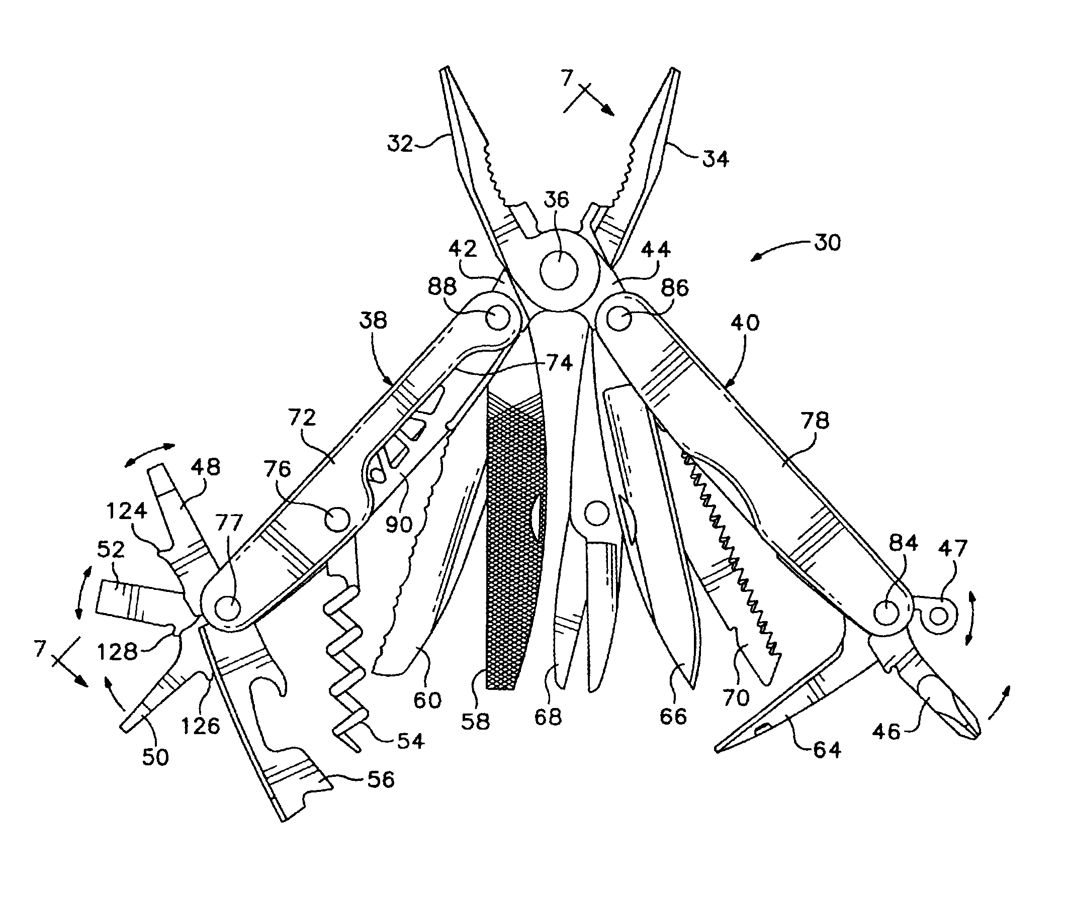
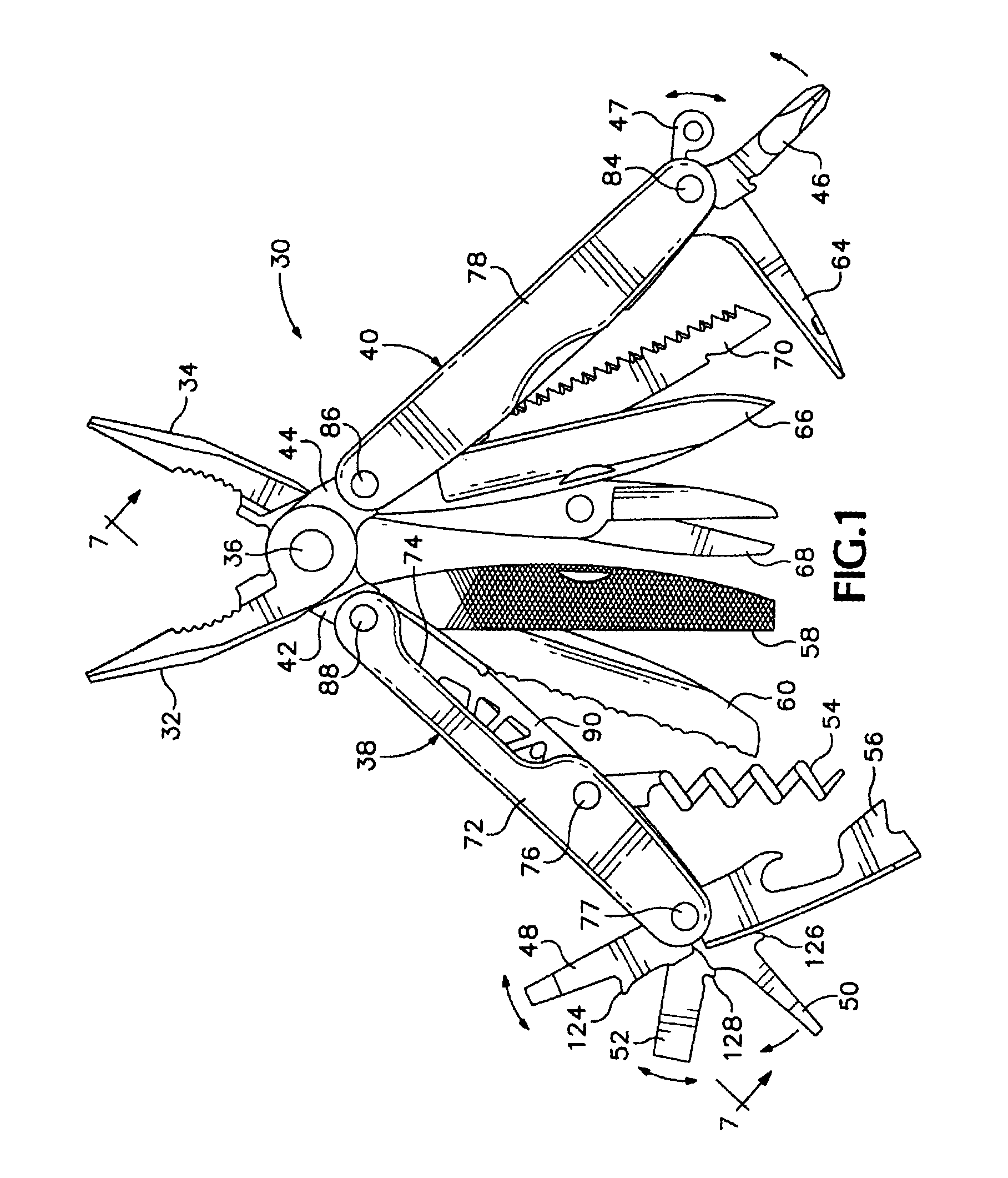
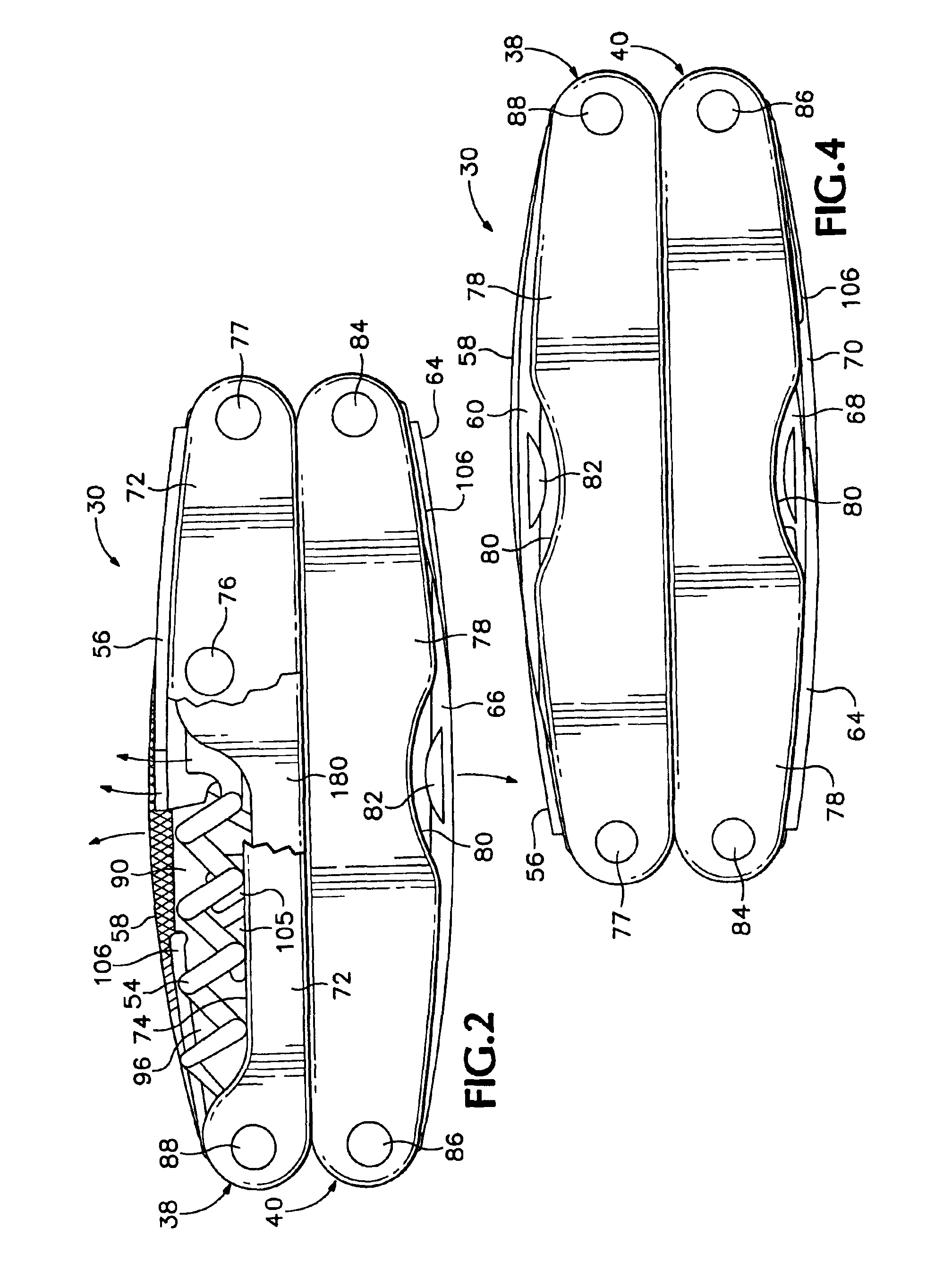
[0063]Referring now to the drawings which form a part of the disclosure herein, a folding multipurpose tool 30 embodying the present invention is shown in FIG. 1. The folding tool 30 includes a pair of pliers including jaws 32 and 34 that cross each other and are interconnected by a pliers pivot joint 36, preferably secured by a rivet. While the pliers jaws 32 and 34 are of the long nose type and include gripping portions and wire cutter portions, it will be understood that other types of pliers jaws might also be included in such a tool instead, as might metal snip jaws or the like, within the limitations of available space. A pair of handles 38, 40 are attached, respectively, to the base portions 42, 44 of the pliers jaws 34, 32. As will be explained in greater detail subsequently, the pliers jaws 32 and 34 can be moved into stowed or folded positions with respect to the handles 38 and 40, and the folding tool 30 can be placed into a folded configuration shown in FIGS. 2, 3, and 4...


PUM


Abstract

A folding multipurpose hand tool including folding pliers or scissors and other tool blades and bits. A pair of handles each has a pivot axle at each end. A base of each pliers jaw or scissors blade is mounted on the pivot axle at one end of a handle, allowing the handles to fold around the jaws to blades to a compact folded configuration of the tool. Each handle has frame side members with attached flanges. Elongate springs lie between the handle frame side members and fit around the flanges, rather than being riveted to the handle frame side members. The springs press against the base of each pliers jaw or other tool blade, to keep each in a folded position or support it in a deployed position. One end of a spring may be hooked around a spring retainer at one end of the handle. The pivot axles interconnect the handle frame side members and the jaws, blades, or tool bits.

Description

[0001]This application is a continuation of U.S. patent application Ser. No. 10 / 062,759, filed Jan. 30, 2002, now U.S. Pat. No. 6,622,328, which is a continuation-in-part of U.S. patent application Ser. No. 09 / 703,369, filed Oct. 31, 2000, now U.S. Pat. No. 6,622,327.BACKGROUND OF THE INVENTION[0002]The present invention relates to folding multipurpose tools, and in particular to such a tool which may include a pair of pliers and several different tool bits and blades and that can be folded small enough to be carried comfortably in one's pocket.[0003]Folding knives and the like including blades or tool bits available to be unfolded from both ends of a handle have typically included springs in the back of the handle to hold each blade in its folded position or in its deployed position by pressing on the base of the blade. Not only do such springs press against the base of a blade to hold it open or closed, but they also bear a considerable axially-directed load when a deployed blade ...

Claims


Application Information

Patent Timeline
Patent Type & Authority Patents(United States)
IPC IPC(8): B25F1/00B26B11/00B25B7/22
CPCB25F1/003B26B11/003B26B11/008B25F1/04
Inventor RIVERA, BENJAMIN C.
Owner LEATHERMAN TOOL GROUP
Why Eureka
Try Eureka