Engraving tool depth control nosepiece for enhancing line uniformity

a technology of depth control and engraving tool, which is applied in the direction of printing, writing aids, decorative arts, etc., can solve the problems of engraving tool not having enough time to plunge all the way down, engraving tool has more time to press against the workpiece, engraving tool is too deep when the tool is used,

Active Publication Date: 2006-08-22
NELSON LANCE
View PDF6 Cites 29 Cited by
  • Summary
  • Abstract
  • Description
  • Claims
  • Application Information

AI Technical Summary

Problems solved by technology

If the rate of travel of the engraving tool across the surface being engraved is slow, the engraving tool has more time to press against the workpiece and therefore plunges deeper into the surface.
When the spring loaded engraving tool is used to engrave very soft materials such as plastic, there is a possibility that the engraving tool will penetrate too deeply when the tool begins its first cut.
The engraving tool will not have sufficient time to plunge all the way down to the specified depth.
Furthermore, the nosepiece does not function as a means for holding a collet for gripping the engraving tool and does not rotate, and also the mechanism that allows the engraving tool to float is unable to rotate and must be held stationary with respect to the cnc machine.
The nosepiece does not provide any engraving tool holding mechanism.
A significant problem with this type of top loading engr...

Method used


Image

  • Engraving tool depth control nosepiece for enhancing line uniformity
  • Engraving tool depth control nosepiece for enhancing line uniformity
  • Engraving tool depth control nosepiece for enhancing line uniformity

Examples


first embodiment

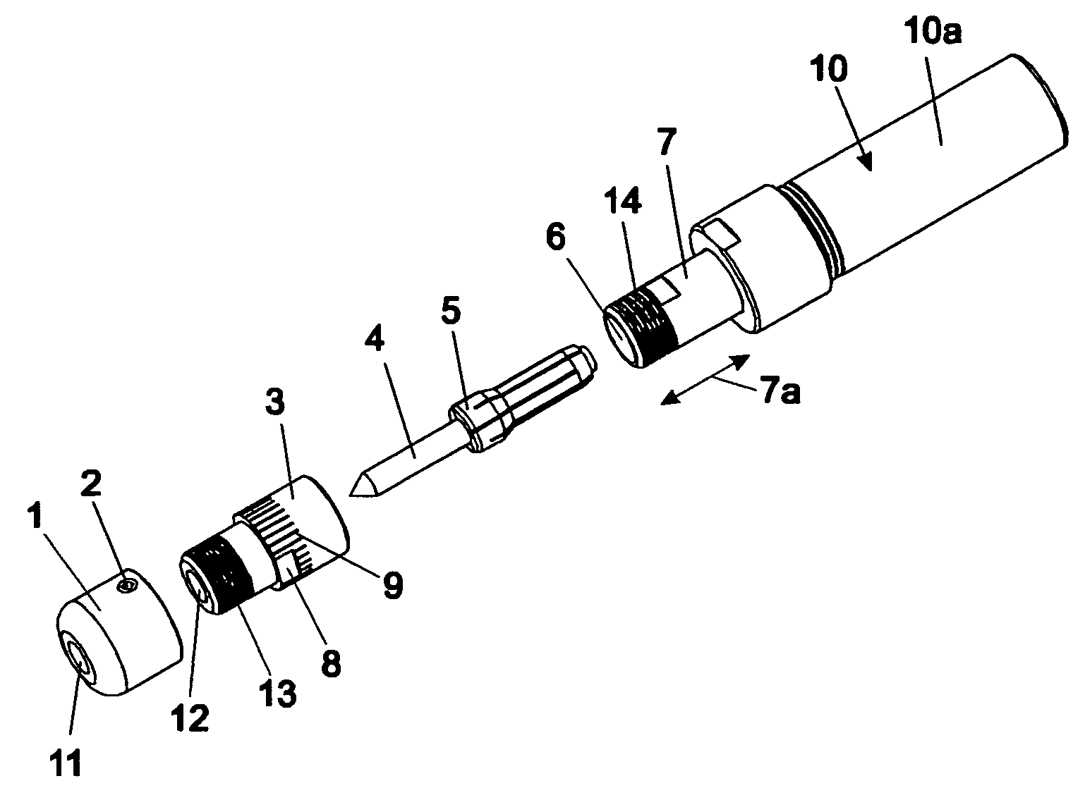
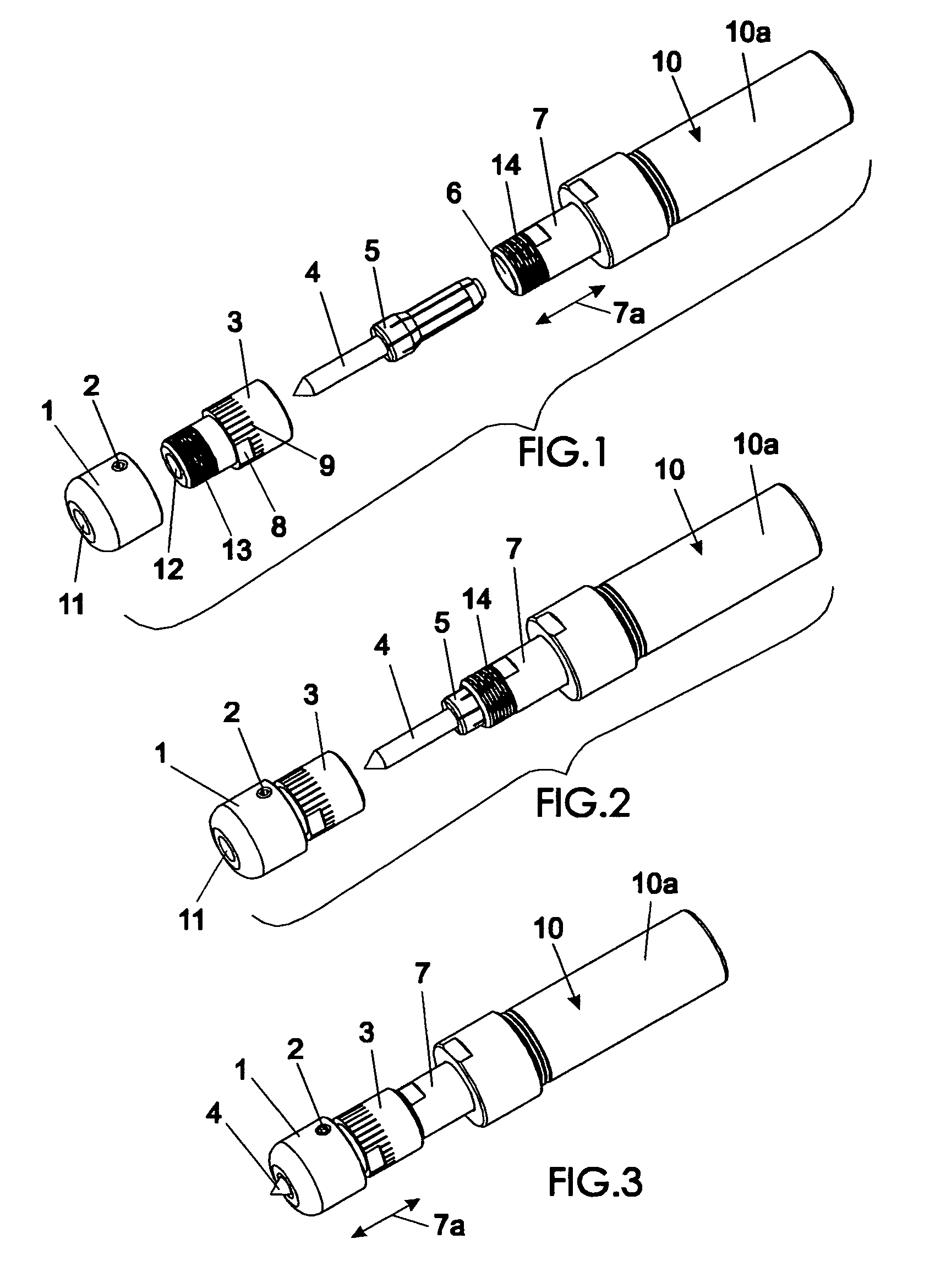
[0014]FIG. 1 is an exploded perspective view of a depth controlling nosepiece and a spring-loaded engraving toolholder,

[0015]FIG. 2 is a partially assembled exploded perspective view of a first embodiment of a depth controlling nosepiece and a spring-loaded engraving toolholder,

[0016]FIG. 3 is an assembled perspective view of a first embodiment of a depth controlling nosepiece and a spring-loaded engraving toolholder,

second embodiment

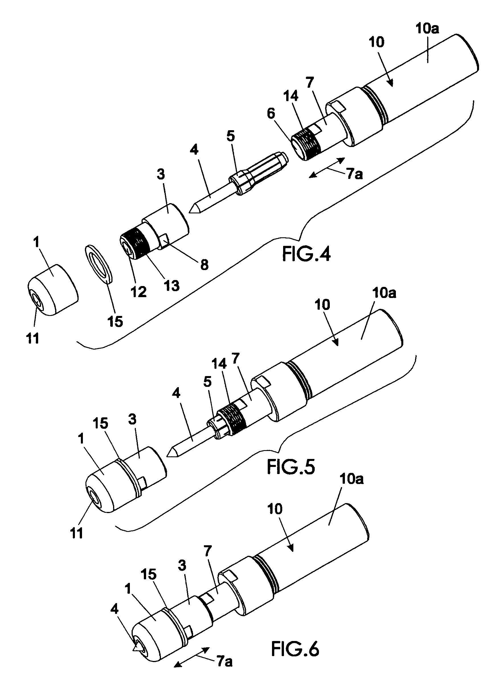
[0017]FIG. 4 is an exploded perspective view of a depth controlling nosepiece and a spring-loaded engraving toolholder,

[0018]FIG. 5 is a partially assembled exploded perspective view of a second embodiment of a depth controlling nosepiece and a spring-loaded engraving toolholder,

[0019]FIG. 6 is an assembled perspective view of a second embodiment of a depth controlling nosepiece and a spring-loaded engraving toolholder,


PUM


Abstract

Engraving tool bit depth controlling nosepiece adjustment devices establish a precise protrusion distance that an engraving tool bit protrudes from the end of the nosepiece of a spring loaded engraving tool, that is in turn inserted within and driven by a standard machine tool such as a cnc type milling machine. One rotational adjustment device establishes the axial position of the nosepiece with respect to a collet nut of the engraving tool and another adjustment device employs annular ring spacers in the form of washers between the nosepiece and collet nut to precisely establish the desired engraving tool bit protrusion distance from the end of the nosepiece. This modification of a spring loaded engraving tool beneficially prevents the engraving tool bit from being able to plunge too deeply into the workpiece, particularly at the start of each engraved line, to thus ensure that all the lines will be consistent.

Description

BACKGROUND OF THE INVENTION[0001]This invention relates to the field of engraving machines.[0002]Engraving with a computer numerically controlled (cnc) type milling machine is typically performed by the following method. A pointed engraving tool is held in a rigid collet or endmill holder and rotated in the spindle of a cnc milling machine. The cnc milling machine controls the depth of engraving by plunging the pointed engraving tool down into the workpiece by a fixed amount. The cnc milling machine then moves the engraving tool across the surface of the part to be engraved at that specific depth. If the material to be engraved is not perfectly flat on the cnc machine table, the engraving will not look even. Some areas of the engraving will be deeper than others and some areas may not be engraved at all.[0003]To overcome this problem, a floating spring loaded engraving tool that is held in a collet and rotated in the spindle of a cnc milling type machine may be used. Such a tool is ...

Claims


Application Information

Patent Timeline
IPC IPC(8): B43L13/00
CPCB44B3/063
Inventor NELSON, LANCE
Owner NELSON LANCE
Why Eureka
Try Eureka