Implantable Leads Having Mechanisms to Impede Over-Rotation of Fixation Mechanisms

a technology of fixation mechanism and mechanism, which is applied in the field of implantable leads, can solve the problems of preventing the shaft from continuing to rotate, limiting the extension of the fixation helices in known leads, and significant damage to the heart, so as to prevent further rotation of the shaft and limit the effect of linear displacemen

Inactive Publication Date: 2010-09-02
PACESETTER INC
View PDF8 Cites 22 Cited by
  • Summary
  • Abstract
  • Description
  • Claims
  • Application Information

AI Technical Summary

Benefits of technology

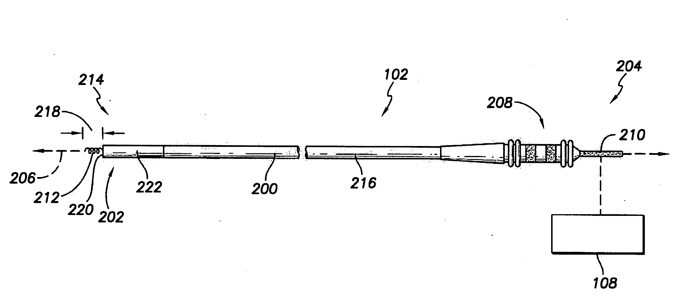
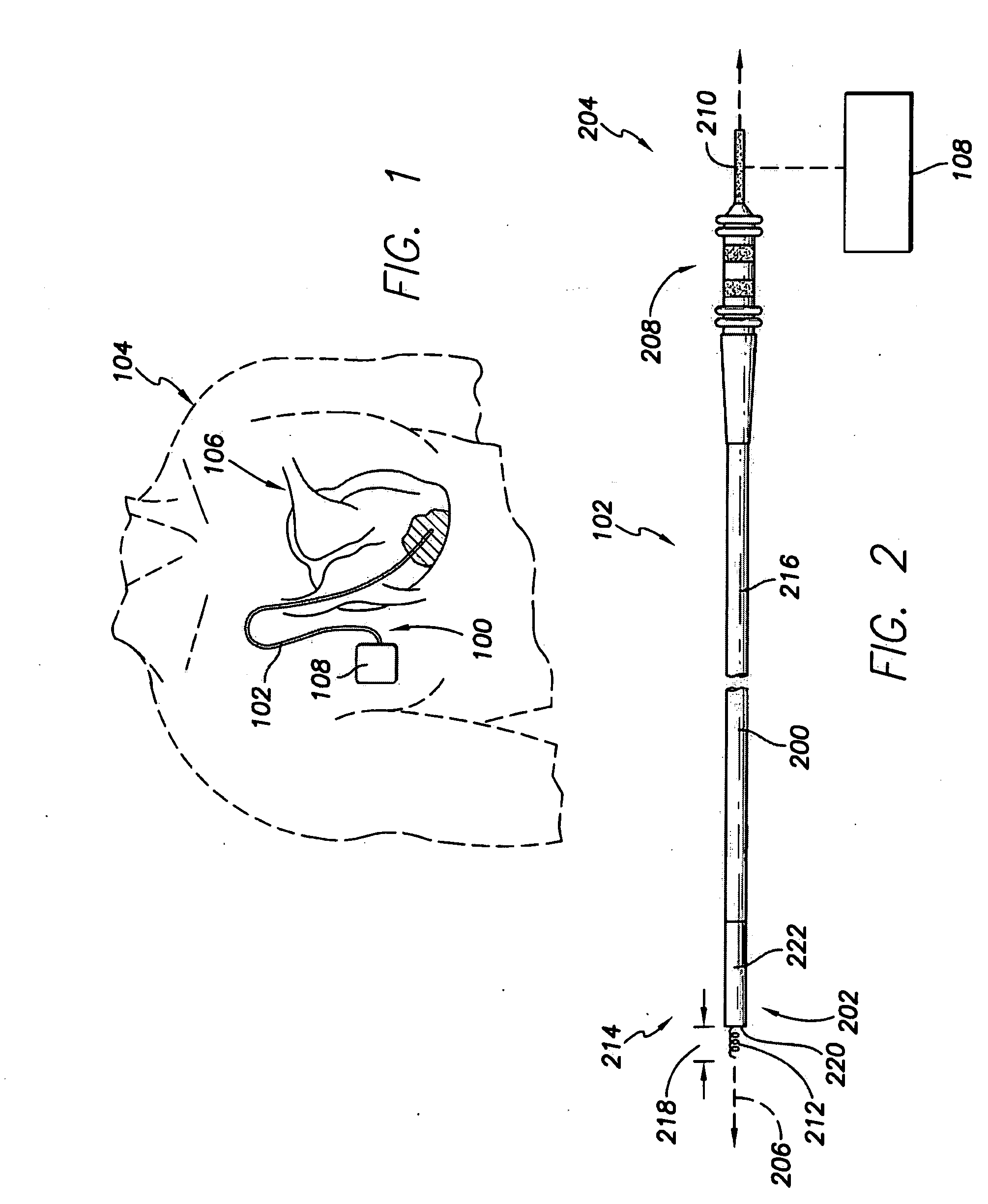
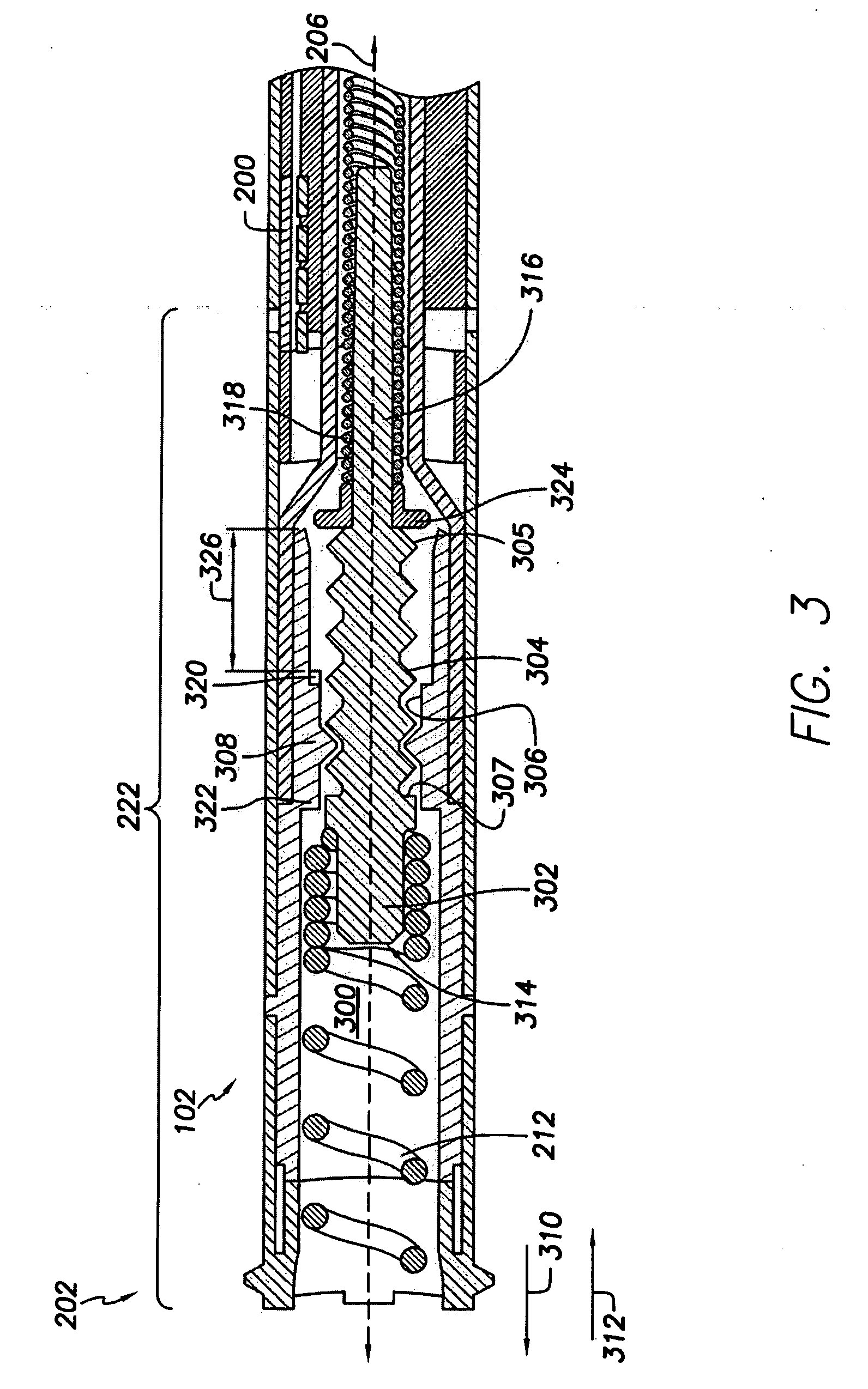
[0007]In one embodiment, an implantable lead is provided. The lead includes a lead body, a header body, a fixation mechanism, a rotatable shaft and a rotation limit element. The lead body extends between a distal end and a proximal end and is configured to be implanted in a patient. The header body is joined to the lead body at the distal end of the lead body. The fixation mechanism is disposed in the header body and is extendable out of the header body for securing the header body to cardiac tissue of the patient. The shaft is provided in the header body and is coupled to the fixation mechanism for translating rotational movement of the shaft into linear displacement of the fixation mechanism. The rotation limit element is disposed in the header body. The rotation limit element engages the header body once the shaft is linearly displaced by a predetermined distance with respect to the header body to prevent further rotation of the shaft and limit additional displacement of the fixation mechanism with respect to the header body.
[0008]In another embodiment, another implantable lead is provided. The lead includes a lead body, a header body, a fixation mechanism and a rotatable shaft. The lead body extends between a distal end and a proximal end and is configured to be implanted in a patient. The header body is joined to the lead body at the distal end of the lead body. The fixation mechanism is disposed in the header body and is extendable out of the header body for securing the header body to cardiac tissue of the patient. The shaft is provided in the header body and is coupled to the fixation mechanism for translating rotational movement of the shaft into linear displacement of the fixation mechanism. The shaft engages the header body once the shaft is linearly displaced by a predetermined distance with respect to the header body to prevent further rotation of the shaft and to limit additional linear displacement of the fixation mechanism with respect to the header body.
[0009]In another embodiment, an implantable lead is provided. The lead includes a lead body, a header body, a fixation mechanism, and a rotatable shaft. The lead body extends between a distal end and a proximal end and is configured to be implanted in a patient. The header body is joined to the lead body at the distal end of the lead body. The fixation mechanism is disposed in the header body and is configured to secure the header body to cardiac tissue of the patient. The shaft is provided in the header body and is coupled to the fixation mechanism. The shaft translates rotational movement of the shaft into linear displacement of the fixation mechanism to extend and retract the fixation mechanism with respect to the header body. The shaft engages the header body once the shaft is linearly displaced by at least one of a predetermined extension distance and a predetermined retraction distance with respect to the header body to prevent further rotation of the shaft and limit additional displacement of the fixation mechanism with respect to the header body.

Problems solved by technology

The extension of fixation helices in known leads is limited to prevent the fixation helix from protruding too far into the cardiac tissue and causing significant damage to the heart.
But, the engagement between the shaft and the inside surfaces of the lead does not prevent the shaft from continuing to rotate.
This rotation with no linear displacement may cause an over-torque or tightening of the threaded engagement between the shaft and the lead.
If the shaft includes an inner post that is engaged by the fixation helix, continued rotation of the shaft will not result in continued linear displacement of the shaft but may cause the fixation helix to become deformed.
The tightening of the threaded connection and the building up of the helix may cause the fixation helix to abruptly move, or jump, when the connector pin and shaft are rotated in the opposing direction of the over-torque.
The jumping of the helix may cause unnecessary damage to the cardiac tissue.
Alternatively, the helix may become stuck or locked in an extended or retracted state and unable to be easily retracted or extended from the locked state.

Method used


Image

  • Implantable Leads Having Mechanisms to Impede Over-Rotation of Fixation Mechanisms
  • Implantable Leads Having Mechanisms to Impede Over-Rotation of Fixation Mechanisms
  • Implantable Leads Having Mechanisms to Impede Over-Rotation of Fixation Mechanisms

Examples


Embodiment Construction

[0021]In the following detailed description, reference is made to the accompanying drawings which form a part hereof, and in which are shown by way of illustration specific embodiments in which the present invention may be practiced. These embodiments, which are also referred to herein as “examples,” are described in sufficient detail to enable those skilled in the art to practice the invention. It is to be understood that the embodiments may be combined or that other embodiments may be utilized, and that structural, logical, and electrical variations may be made without departing from the scope of the present invention. For example, embodiments may be used with a pacemaker, a cardioverter, a defibrillator, and the like. The following detailed description is, therefore, not to be taken in a limiting sense, and the scope of the present invention is defined by the appended claims and their equivalents. In this document, the terms “a” or “an” are used, as is common in patent documents,...


PUM


Abstract

An implantable lead includes a lead body, a header body, a fixation mechanism, a rotatable shaft and a rotation limit element. The fixation mechanism is disposed in the header body and is extendable out of the header body for securing the header body to cardiac tissue of the patient. The shaft is provided in the header body and is coupled to the fixation mechanism for translating rotational movement of the shaft into linear displacement of the fixation mechanism. The rotation limit element is disposed in the header body. The rotation limit element engages the header body once the shaft is linearly displaced by a predetermined distance with respect to the header body to prevent further rotation of the shaft and limit additional displacement of the fixation mechanism with respect to the header body.

Description

FIELD OF THE INVENTION[0001]The various embodiments described herein generally relate to implantable leads, and more particularly to implantable leads having extendable and retractable fixation mechanisms.BACKGROUND OF THE INVENTION[0002]An implantable medical device is implanted in a patient to, among other things, monitor electrical activity of a heart and to deliver appropriate electrical therapy as required. Implantable medical devices (“IMDs”) include for example, pacemakers, cardioverters, defibrillators, implantable cardioverter defibrillators (“ICD”), and the like. The electrical therapy produced by an IMD may include, for example, pacing pulses, cardioverting pulses, and / or defibrillator pulses to reverse arrhythmias (e.g. tachycardias and bradycardias) or to stimulate the contraction of cardiac tissue (e.g. cardiac pacing) to return the heart to its normal sinus rhythm. The devices include leads that are implanted to cardiac tissue to monitor the activity of the heart and ...

Claims


Application Information

Patent Timeline
Patent Type & Authority Applications(United States)
IPC IPC(8): A61N1/05
CPCA61N1/0573
Inventor CASELLA, CHRISTINAHILL, ROLFJARL, PER
Owner PACESETTER INC
Why Eureka
Try Eureka