Shuttle Stop Force Limiter

a technology of stop force limiter and rotary input member, which is applied in the direction of power amplification, transportation and packaging, etc., can solve the problems of preventing the movement of the other control surface, stalling of the pdu, etc., and achieves the effect of preventing further rotation of the rotary input member and preventing damage to the actuator or the aircra

Active Publication Date: 2010-08-26
PARKER INTANGIBLES LLC
View PDF24 Cites 25 Cited by
  • Summary
  • Abstract
  • Description
  • Claims
  • Application Information

AI Technical Summary

Benefits of technology

[0006]The present invention provides an actuator characterized by the use of a shuttle that shifts in response to an overload. The shuttle is movable axially relative to a rotary input member by continued rotation of the rotary input member so that a stop on the shuttle moves from an ambush position allowing free rotation of the rotary input member to a blocking position preventing further rotation of the rotary input member. In this way, the shuttle can be used to prevent rotation of a rotary input member during an overload of a control surface, thereby preventing damage to the actuator or aircraft.

Problems solved by technology

The actuators have included, for example, a force limiting device that limits the amount of force that can be applied to the control surface and further causes stalling of the PDU to prevent movement of the other control surfaces.

Method used


Image

  • Shuttle Stop Force Limiter
  • Shuttle Stop Force Limiter
  • Shuttle Stop Force Limiter

Examples


Embodiment Construction

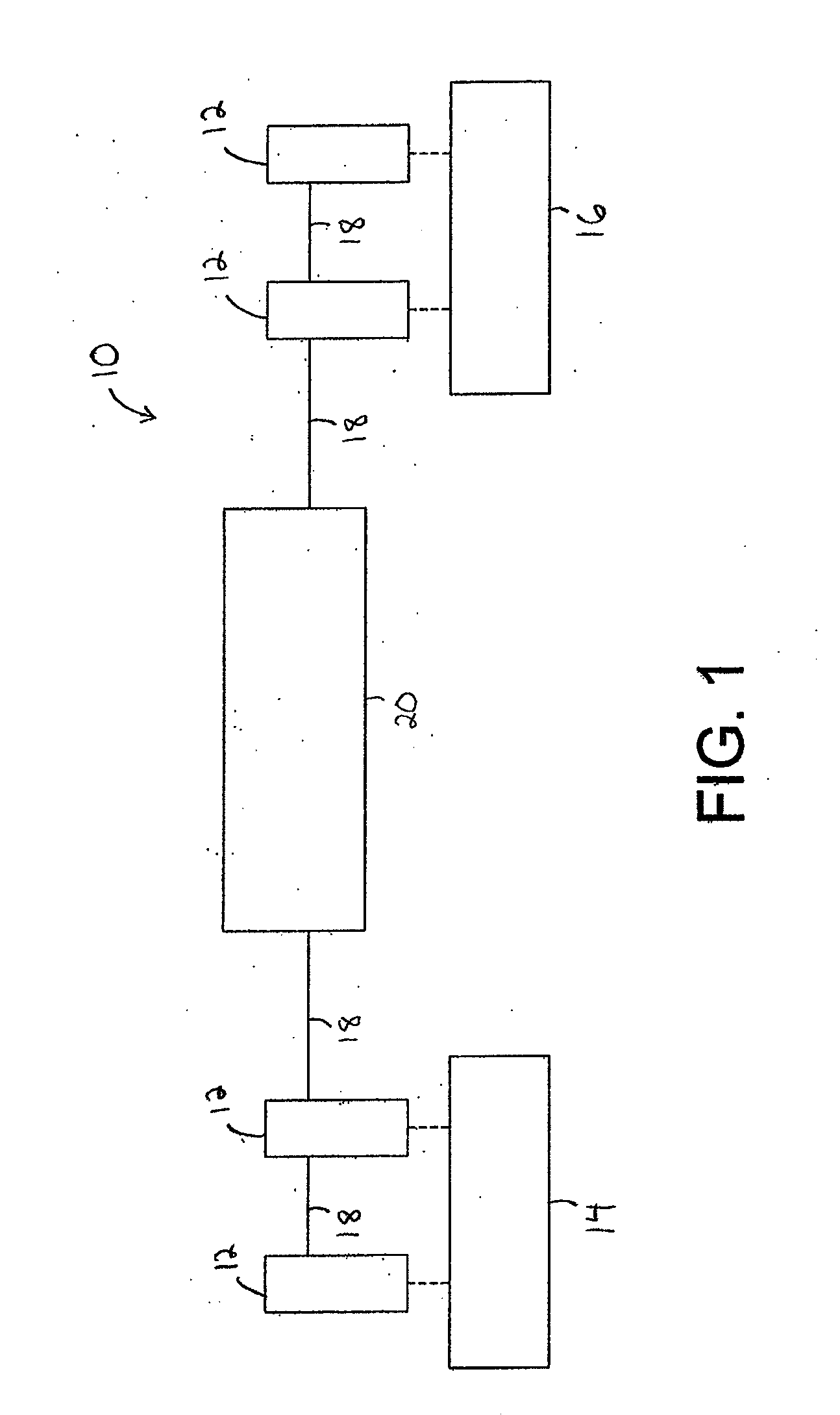
[0026]Referring now in detail to the drawings and initially to FIG. 1, an exemplary flap system 10 can be seen to comprise four flap actuators 12 for driving two flap panels 14 and 16. As will be appreciated, the number of flap panels and actuators may be varied for a given application, but usually there will be one or more flap panels on each wing and a like number on the other wing. Each flap panel may be driven by one or more actuators 12. In the illustrated embodiment, the flap panels 14 and 16 are driven by two actuators each. It will also be appreciated that the principles of the invention may be applied to any system where linear mechanical actuators are used and load limiting is required, and the use herein of the term control surface panel is intended to encompass any type of controlled item including but not limited to; flaps, slats, doors, stabilizers and other similar devices. The following description, however, will refer to flap panels, it being appreciated that such d...


PUM


Abstract

The present invention provides an actuator characterized by the use of a shuttle that shifts in response to an overload. The shuttle is movable axially relative to a rotary input member by continued rotation of the rotary input member so that a stop on the shuttle moves from an ambush position allowing free rotation of the rotary input member to a blocking position preventing further rotation of the rotary input member. In this way, the shuttle can be used to prevent rotation of a rotary input member during an overload of a control surface, thereby preventing damage to the actuator.

Description

RELATED APPLICATIONS[0001]This application claims the benefit of U.S. Provisional Application No. 61 / 154,476 filed Feb. 23, 2009, which is hereby incorporated herein by reference.FIELD OF INVENTION[0002]The present invention relates generally to actuation systems, and more particularly to an aircraft flight control actuation system.BACKGROUND[0003]Modern aircraft wings often include a series of movable flight control surfaces, such as flaps or slats that can be selectively extended or retracted to modify the lift producing characteristics of the wings. Extension and retraction of such flaps or slats is accomplished by a flight control actuation system mounted in the wing.[0004]A typical actuation system includes a series of actuators spaced along the span of each wing, and operably connected to move one or more individual flight control surfaces. Adjacent actuators are connected to each other by drive shafts to form a chain of actuators and shafts extending along the span of the win...

Claims


Application Information

Patent Timeline
Patent Type & Authority Applications(United States)
IPC IPC(8): B64C13/34F16H1/16
CPCB64C13/50B64D2045/001F16H1/16F16H25/2021Y10T74/19828F16H2025/209F16H1/06Y10T74/18696Y10T74/18688F16H25/2454B64C13/34
Inventor FLATT, JAMES E.MCKAY, TED ALEXANDER
Owner PARKER INTANGIBLES LLC
Why Eureka
Try Eureka