Cutting tool and tool head

a cutting tool and tool head technology, applied in the direction of sleeve/socket joint, turning apparatus, milling equipment, etc., can solve the problems of damage to workpieces and the rejection of expensive parts

Active Publication Date: 2006-03-23
SECO TOOLS AB
View PDF9 Cites 28 Cited by
  • Summary
  • Abstract
  • Description
  • Claims
  • Application Information

AI Technical Summary

Benefits of technology

[0004] According to another aspect of the present invention, a tool head includes a cutting portion and a mounting portion, the mounting portion including an axial stop surface, and a radial stop surface. Dimensions and tolerances of the axial stop surface and the radial stop surface are selected such that the axial stop surface will abut an axial stop on a toolholder to prevent axial movement of the to...

Problems solved by technology

In the case, for example, of a rotating tool, an insert or tool head that is displaced axially relative to a ro...

Method used


Image

  • Cutting tool and tool head
  • Cutting tool and tool head
  • Cutting tool and tool head

Examples


Embodiment Construction

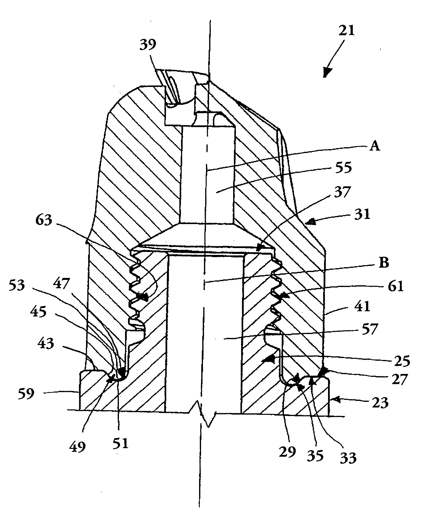
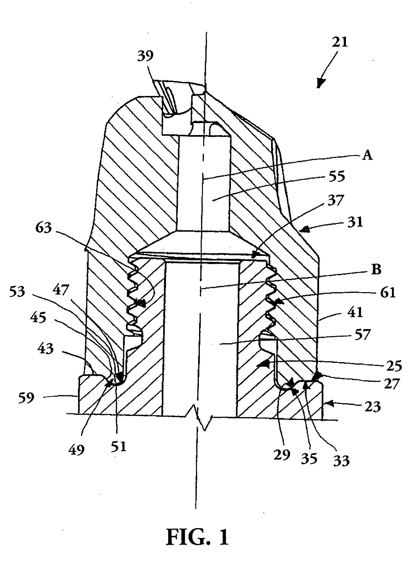
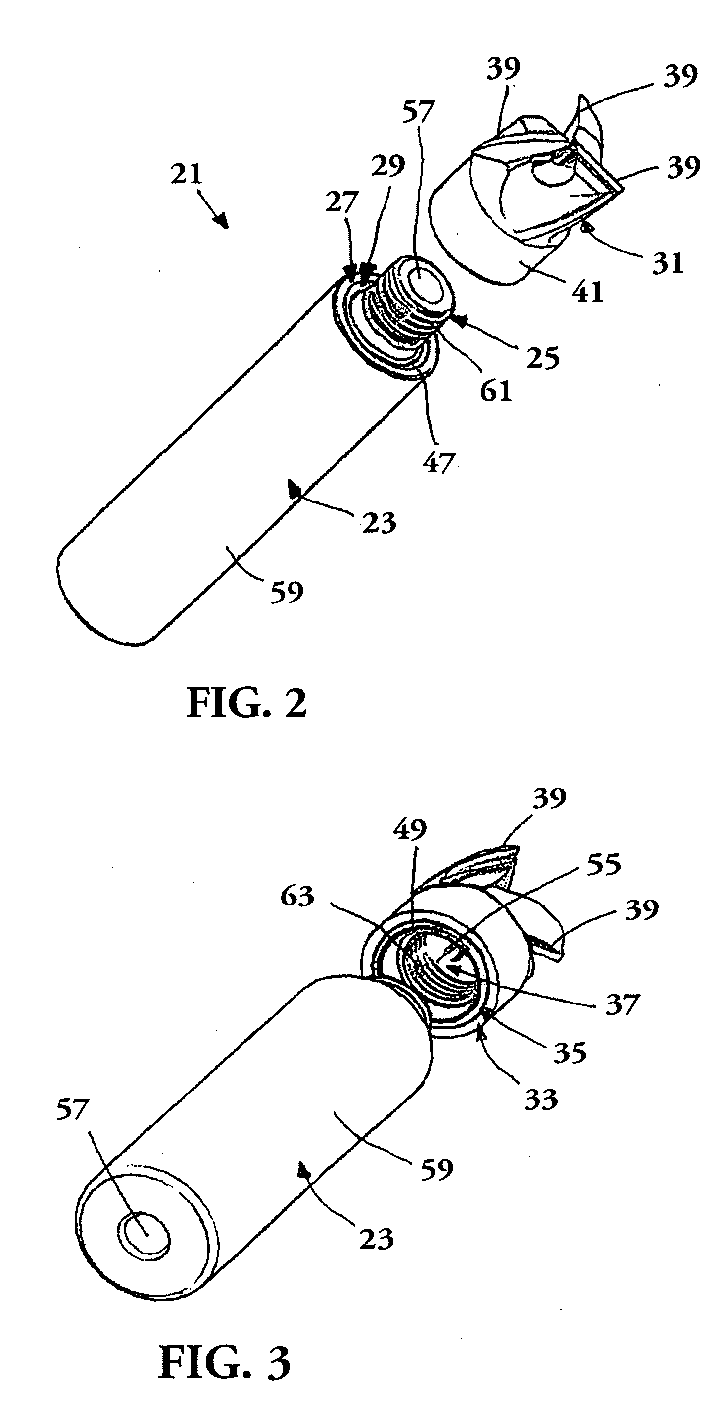
[0010] A tool 21 according to an embodiment of the present invention is shown in FIGS. 1-3. The tool 21 includes a toolholder in the form of a shank 23 including an end portion 25. The end portion 25 includes an axial stop 27, and a radial stop 29. The shank 23 shown here is a circular cylinder, however, the shank may have other shapes as desired, such as, for example, a hexagonal shape, a splined shape, etc. The present invention has application to all manner of tools to which replaceable cutting heads or inserts are attachable, such as milling, drilling, boring, turning, and similar tools. The embodiment illustrated in FIGS. 1-3 is a rotating tool.

[0011] The tool 21 also includes a replaceable insert or tool head 31 having an axial stop surface 33, and a radial stop surface 35. In the embodiment of FIGS. 1-3, the end portion 25 is at least partially receivable in an internal opening 37 in the tool head 31 up to a position at which the axial stop 27 abuts the axial stop surface 33...


PUM

PropertyMeasurementUnit
Angleaaaaaaaaaa
Diameteraaaaaaaaaa
Distanceaaaaaaaaaa

Abstract

The present invention relates to a tool head preferably for milling. The tool head is connectable to a toolholder. The tool head includes a cutting portion and a mounting portion. The mounting portion includes an axial stop surface and a radial stop surface. Dimensions and tolerances of the axial stop surface and the radial stop surface are selected such that the axial stop surface will abut an axial stop on the toolholder to prevent axial movement of the toolholder relative to the tool head beyond the axial stop surface and the radial stop surface will be disposed proximate a radial stop of the toolholder to limit radial movement of the tool head relative to the toolholder when an integral fastening portion of the tool head and an integral fastening portion of the toolholder are fastened directly to one another and the axial stop surface and the axial stop abut.

Description

BACKGROUND AND SUMMARY [0001] It is often extremely important in operations such as machining of metal or other workpieces that the location of a cutting edge of a cutting tool be precisely controlled and controllable. Complex machinery is provided to mill, drill, bore, or otherwise perform shaping operations on workpieces by precisely controlling the location of a cutting tool relative to the workpiece. Cutting tools often include replaceable inserts or cutting heads that are attached to permanent toolholders such as shanks that are moved relative to the workpiece. [0002] The accuracy of the mounting of the cutting inserts or heads relative to the toolholder is a factor in the accuracy of the operation to be performed on the workpiece. In the case, for example, of a rotating tool, an insert or tool head that is displaced axially relative to a rotating shank to which it is attached can damage the workpiece and may necessitate the rejection of an expensive part. It is therefore desir...

Claims


Application Information

Patent Timeline
IPC IPC(8): B23B51/00B23BB23B31/11B23C5/10
CPCB23B31/11B23B31/1122B23C5/109B23C2210/02Y10T407/1906Y10T408/90993Y10T279/16Y10T408/957B23C2210/03B23C2240/32
Inventor JONSSON, CHRISTERHOGRELIUS, BENGTERIKSSON, JANEJDERKLINT, CHRISTERBERGLOW, CARL-ERIKKOSKINEN, JORMABOMAN, JONAS
Owner SECO TOOLS AB
Why Eureka
Try Eureka